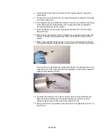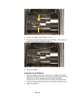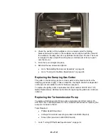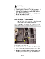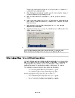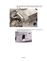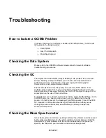
10. Change the position of the ionization mode switch on the manifold electronics
enclosure to the left (internal) position.
Changing the Transfer line Position from Internal to
External
1. To move the 4000 MS away from the GC, go to page 37.
2. Unplug the transfer line heater cable from connector J37 on the bulkhead.
3. Be sure the transfer line is cool; then remove the transfer line assembly
(including the weldment) from the manifold by loosening the four captive
screws holding it in place. Be sure not to lose the sealing O-ring.
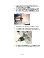
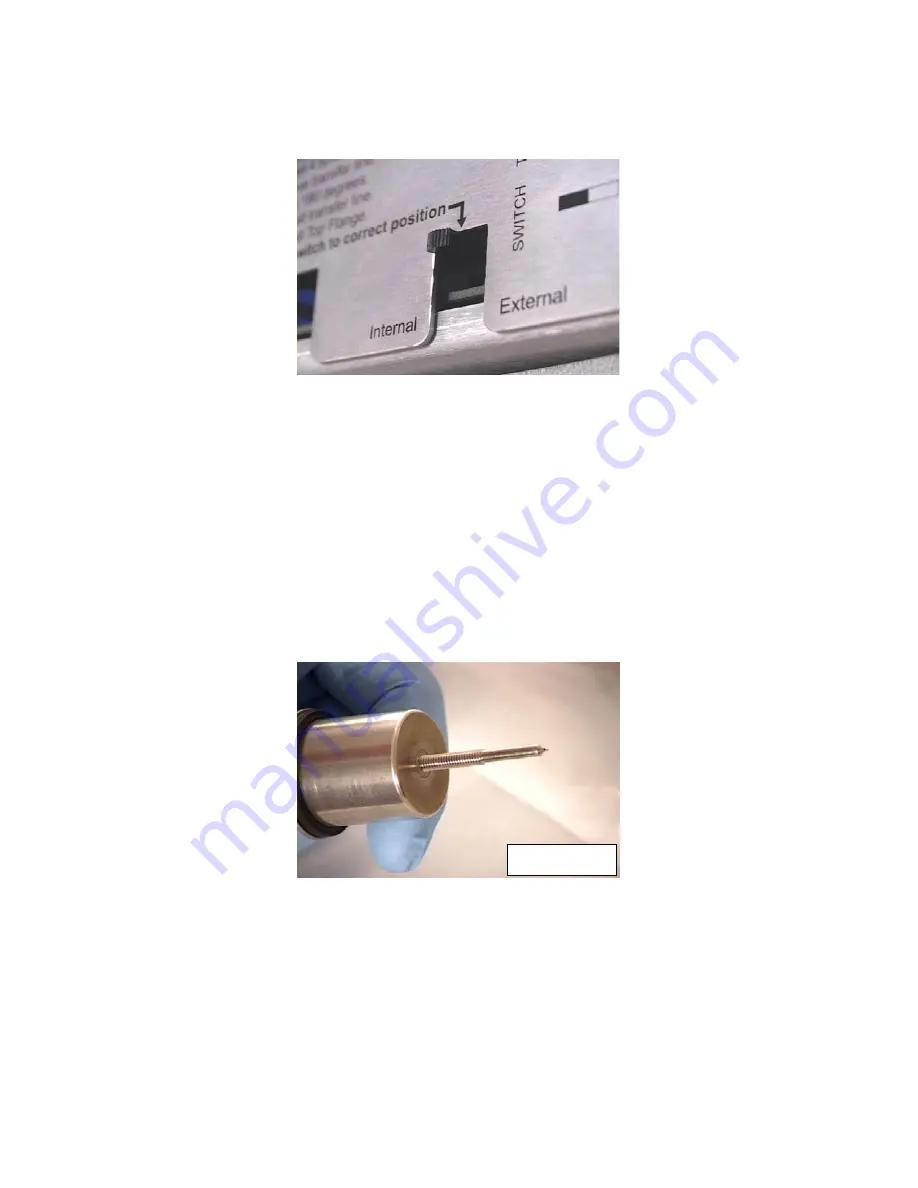
4. Remove the internal tip and replace it with the long metal external transfer
line tip provided with the external source. If necessary, a 3/16" wrench can
be used to stabilize the transfer line and a 5/16" wrench used to remove the
tip.
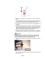
External Tip
5. Loosen the brass nut at the GC side of the transfer line and then reposition
the column until it extends 1 mm from the end of the tip. If the column won’t
move, it may be necessary to cut off the column before the transfer line,
remove the ferrule from the brass nut, and reinsert the column using a new
ferrule (as described in the column replacement procedure).
6. Replace the transfer line assembly, positioning it towards the front of the
instrument, and tighten the four screws. Be sure that the O-ring is clean and
properly seated in the manifold groove (that there are no kinks or twists).
87 of 127
Summary of Contents for 4000 GC
Page 4: ......
Page 40: ...6 of 127...
Page 77: ...3 Check source connection pins for proper alignment and straighten as necessary 43 of 127...
Page 124: ...90 of 127...
Page 148: ...114 of 127...

