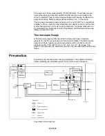
compares the desired and actual amount of the RF voltage and adjusts the gain
of an RF amplifier to cause the actual RF voltage to equal the desired RF
voltage. Since the high voltage required at the ion trap exceeds the capabilities of
conventional electronic amplifiers, a resonant LC circuit consisting of the RF coil
and the ion trap capacitance is used. At resonance, the RF voltage at the ion trap
end of the coil is about 150 times that at the RF generator circuit end of the coil.
Ion Detection Board
The ion detection board contains key elements of the electronics associated with
detecting ions by either the electron multiplier or ion gauge. The board contains a
power supply that applies voltage to the cathode of the electron multiplier. That
supply consists of a chain of voltage multiplier circuits that are switched between
–800 and –3000 volts by a multiplier on signal from the controller. The ion
detection board also has the emission current regulation circuitry for the ion
gauge, as well as the electronics to obtain and condition its vacuum signal.
Ion Amplifier
The ion amplifier converts the current received from the electron multiplier to
voltage that can then be read by the controller board analog to digital converter.
This amplifier boosts the signal by a factor of 10
7
. To maximize the bandwidth,
the amplifier is mounted on the side of the vacuum manifold as close to the
multiple output feed-through as possible.
Electronic Flow Control
An electronic flow controller (EFC) controls the flow rate of helium damping gas
in external ionization mode. The EFC maintains the proper flow using a closed
loop feedback control system. The flow set point is set through a digital to analog
converter (DAC) that receives its setting from the controller board. The control
electronics then reads the flow by measuring the pressure across a known orifice
using two pressure transducers. It sets the required flow using a proportional
solenoid valve. The relationship between flow and differential pressure is factory
calibrated. Ambient temperature is measured to compensate for flow differences
with temperature. The EFC also is used to control the state of the helium cutoff
valve at the manifold. This valve is closed if excess getter temperature is
detected or if the helium inlet pressure drops below 20 psi.
Power Input Subsystem and Turbomolecular Pump
Controller
The power input subsystem contains the following circuits and switches:
•
Main power switch
•
SERVICE
switch
•
Line
voltage
switches
25 of 127
Summary of Contents for 4000 GC
Page 4: ......
Page 40: ...6 of 127...
Page 77: ...3 Check source connection pins for proper alignment and straighten as necessary 43 of 127...
Page 124: ...90 of 127...
Page 148: ...114 of 127...


