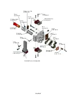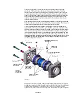
There is a single hole in the center of both the entrance and exit end cap
electrodes. The hole in the entrance electrode allows the entry of ionizing
electrons when the system is configured for internal ionization. The hole in the
exit end cap allows the exit of ions to the detector. There are also holes in the
edge of the end caps in which banana plugs are placed that make contact with
springs that carry supplemental waveform signals. One of these holes in the
entrance end cap also acts as the sample inlet to the ion trap in internal and
hybrid ionization modes.
Four identical quartz or silica-coated spacers separate the central ring electrode
from the entrance and exit end cap and from the trap oven plates. The trap oven
and its clamping plate hold the electrodes and spacers in place.
The RF generator assembly provides high voltage 1 MHz RF voltage that is
applied to the RF ring electrode through a feedthrough on the underside of the
vacuum manifold. Under the proper RF voltage, the ion trap electrodes create a
three-dimensional, hyperbolic electric field. This field is capable of trapping the
ions in stable, aperiodic orbits. In the presence of helium damping gas, the ions
are cooled towards the center of the trap. As the RF voltage increases, the ion
trajectories become unstable in increasing order of mass to charge ratio. The ion
trap ejects the ions and sends them to the conversion dynode and then to the
electron multiplier for detection.
Spring
21-719939-00
Quartz, Silco Spacer
03-930535-02
RF Electrode,
Silco Coated
03-931675-93
Trap Oven, Entrance Half
03-931028-01
Silco End Cap Electrode
03-931644-93
Silco End Cap
Electrode
03-931644-93
Banana Plug
51-15194-00
Supplemental Waveform Plug
03-931667-01
Thumbscsrew
03-931672-01
Trap Oven, Exit Half
03-931028-02
Quartz,
Silco Spacer
03-930535-02
Ion Trap
During mass analysis, a dipole voltage at the trapping RF frequency is applied
across the end caps to offset the ions from the center of the trap. Two additional
supplemental waveforms are applied to the end caps. The dipole signal is
applied out of phase across the end caps while the quadrupole signal is applied
15 of 127
Summary of Contents for 4000 GC
Page 4: ......
Page 40: ...6 of 127...
Page 77: ...3 Check source connection pins for proper alignment and straighten as necessary 43 of 127...
Page 124: ...90 of 127...
Page 148: ...114 of 127...

