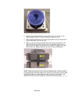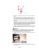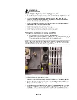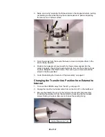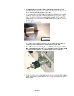
23. Position the transfer line so that the heater cable aligns with the slot on the
right side of the transfer line.
24. Remove the analyzer assembly during this step to avoid damaging the
transfer line tip. Insert the transfer line into the manifold, and install the clip
on the transfer line into the holes provided.
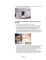
25. Gently push the transfer line toward the manifold, and rotate the collar in the
clockwise direction until the bayonet lock engages.
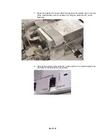
26. Route the transfer line heater cable below the transfer line, through the white
retainer and under the thermocouple vacuum gauge. Then plug the transfer
line heating cable to connector J37.
27. Replace the 4000 MS top cover.
•
Gently push the mass spectrometer toward the GC, until the transfer line
nut is visible inside the GC oven. Take caution not to damage rear
pneumatics lines. The boot should fit snugly into the hole on the side of
the GC oven.
•
Turn the GC oven on through its keyboard by pressing the Column Oven
button and the blue soft key entitled Turn Oven On.
•
Go to “Turning On the Mass Spectrometer” on page 46.
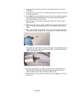
28. After the trap, source, and manifold temperatures have reached their
setpoints, condition the new column to prevent MS contamination.
Replacing Consumable Components
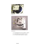
Replacing External Source Filaments
•
Go to “Turning Off the Mass Spectrometer” on page 34.
•
Go to “Removing the Analyzer Assembly” on page 37.
•
Go to “Removing the Source/Ion Trap Assembly” on page 40.
75 of 127
Summary of Contents for 4000 GC
Page 4: ......
Page 40: ...6 of 127...
Page 77: ...3 Check source connection pins for proper alignment and straighten as necessary 43 of 127...
Page 124: ...90 of 127...
Page 148: ...114 of 127...

