Failing to remove the transfer line before removing the trap may result in
damage to the transfer line tip.
The power board supplies power to the cartridge heater via a transfer line heater
cable. The heater cable projects out from one end of the transfer line. It then
plugs into a soft-shell connector on the top of the power board panel.
The transfer line temperature is set in the Temperature Dialog in System Control.
The maximum temperature that the transfer line can sustain is 350 °C; the
minimum temperature depends on the GC oven and trap temperatures. In
general, the transfer line temperature can be set as much as 30 °C below the
maximum column operating temperature and not cause adverse
chromatographic effects (e.g., retention time shifts or peak broadening).
After the sample stream passes through the transfer line it is ionized either in the
ion trap or in the external source.
Analyzer
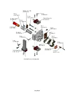
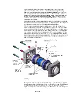
The Analyzer consists of an Internal Ionization Assembly or External Source, the
Ion Trap and a Conversion Dynode/Electron Multiplier Detector. All components
except the detector are mounted on a flange, which also contains an enclosure
holding electronics related to the analyzer. For the purposes of this manual, this
assembly is referred to as the “
Analyzer Assembly
”. The Internal Ionization
Assembly or External Source is attached to the Ion Trap Assembly. This
combination is referred to as the “
Source/Ion Trap Assembly
” in this manual.
Internal Ionization Configuration
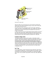
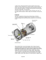
When the system is in internal ionization configuration, ions are generated
directly in the ion trap. Electrons for ionization are produced and gated by an
internal ionization source that resides just outside the ion trap’s entrance
electrode. The source consists of a filament assembly and electron gate
electrode with associated mounting hardware. It is held on a U shaped structure,
which is also used to hold collimating magnets for external ionization.
10 of 127
Summary of Contents for 4000 GC
Page 4: ......
Page 40: ...6 of 127...
Page 77: ...3 Check source connection pins for proper alignment and straighten as necessary 43 of 127...
Page 124: ...90 of 127...
Page 148: ...114 of 127...

