5.1
Installation
31
5
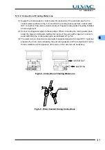
5.1.3.2 Connection of Cooling Water Line
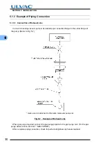
(1) Supply the coolant water to coolant water IN connection of the solenoid valve for the
coolant water as shown in Fig. 5-8, and drain the cooling water pipe from coolant water
OUT connection. The valve to isolate (Lockout / Tagout) cooling water should be installed
at user equipment.
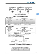
(2) Connect cooling water pipes to these pumps. When connecting the cooling water pipes,
screw the pipe joint while also holding the nozzle of the pump with a spanner in order to
avoid deforming the cooling water pipe, as illustrated in Fig. 5-9.
(3) The water valve is closed and coolant water supply is stopped at AC input OFF. Customer
prepares the cross valve and piping, the pump is bypassed, and the coolant water can be
thrown. Addition and the pipework of the valve in the customer are necessary.
Fig.5-8
Connection of Cooling Water Line
Fig.5-9
Water Coolant Tubing Connections
PIPE JOINT
Summary of Contents for UTM3400 Series
Page 2: ...This page is intentionally left blank...
Page 10: ...viii Location of Label...
Page 20: ...6 1 1 2 Descriptions This page is intentionally left blank...
Page 21: ...2 2IDENTIFICATION AND FUNCTION 2 1 Pump Main Unit 2 2 Control Panel 2 3 External I F Panel...
Page 30: ...16 3 3 3 Controller This page is intentionally left blank...
Page 36: ...22 4 4 3 Standards Fulfilled This page is intentionally left blank...
Page 50: ...36 5 5 5 Notes on Transportation This page is intentionally left blank...
Page 72: ...58 6 6 8 Communication Specifications This page is intentionally left blank...
Page 73: ...7 7GAS PURGE...
Page 82: ...68 8 8 6 Turbo Molecular Pump Return Request This page is intentionally left blank...
Page 95: ...10 10WARRANTY CLAUSES...
Page 98: ...84 10 This page is intentionally left blank...
Page 100: ...Index Index 2 This page is intentionally left blank...

