SECTION 2
IDENTIFICATION AND FUNCTION
8
2
2.1
Pump Main Unit
Fig.2-1
Pump Main Unit
(1) INLET FLANGE ............................... Inlet flange, joint the turbo molecular pump,
VG300, VG350 and ISO320F are available.
(2) PORT FOR GAS PURGE................ Gas purge adaptor port, KF10, UJR 6.35, Swagelok
Φ6.35 and 4-VCR are available.
(Refer to Section 7 "GAS PURGE".)
(3) OUTLET FLANGE ........................... Outlet flange, connect a backing vacuum pump or its
related pipe connection, KF40.
(4) COOLING WATER PIPELINE......... Cooling water pipe connector, Rc1/4.
(5) WATER VALVE ............................... For protection from dew.
(Refer to Section 5.3 "Preparation for Operation".)
This valve is normally closed valve. (opened when
energizing, and closed when not energizing.)
(6) CONTROL PANEL .......................... AC input connector, power switch and local control
switch.
(Refer to Section 2.2 "Control Panel".)
(7) External I/F PANEL ......................... Communication interface.
(Refer to Section 2.3 "External I/F Panel".)
Summary of Contents for UTM3400 Series
Page 2: ...This page is intentionally left blank...
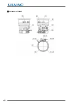
Page 10: ...viii Location of Label...
Page 20: ...6 1 1 2 Descriptions This page is intentionally left blank...
Page 21: ...2 2IDENTIFICATION AND FUNCTION 2 1 Pump Main Unit 2 2 Control Panel 2 3 External I F Panel...
Page 30: ...16 3 3 3 Controller This page is intentionally left blank...
Page 36: ...22 4 4 3 Standards Fulfilled This page is intentionally left blank...
Page 50: ...36 5 5 5 Notes on Transportation This page is intentionally left blank...
Page 72: ...58 6 6 8 Communication Specifications This page is intentionally left blank...
Page 73: ...7 7GAS PURGE...
Page 82: ...68 8 8 6 Turbo Molecular Pump Return Request This page is intentionally left blank...
Page 95: ...10 10WARRANTY CLAUSES...
Page 98: ...84 10 This page is intentionally left blank...
Page 100: ...Index Index 2 This page is intentionally left blank...


