5.1
Installation
27
5
5.1.2.1 Instruction and Lifting Method
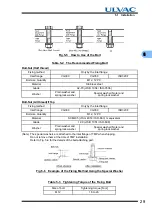
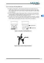
This product lift the pump in the manner shown in Fig. 5-2.
Fig.5-2
Lifting Method
Table 5-1
Eyebole Size
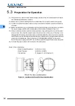
The center of gravity of the pump is shown in Fig. 5-3. Fix securely to avoid moving or falling
down in the event of an earthquake.
Fig.5-3
Center of Gravity of the Pump
Position
Eyebolt size
Number of eyebolts
Remark
Vertical
M12
2
Not bundled items
Inverted
M8
4
Vacuum
chamber
Vacuum
chamber
PUMP
PUMP
Summary of Contents for UTM3400 Series
Page 2: ...This page is intentionally left blank...
Page 10: ...viii Location of Label...
Page 20: ...6 1 1 2 Descriptions This page is intentionally left blank...
Page 21: ...2 2IDENTIFICATION AND FUNCTION 2 1 Pump Main Unit 2 2 Control Panel 2 3 External I F Panel...
Page 30: ...16 3 3 3 Controller This page is intentionally left blank...
Page 36: ...22 4 4 3 Standards Fulfilled This page is intentionally left blank...
Page 50: ...36 5 5 5 Notes on Transportation This page is intentionally left blank...
Page 72: ...58 6 6 8 Communication Specifications This page is intentionally left blank...
Page 73: ...7 7GAS PURGE...
Page 82: ...68 8 8 6 Turbo Molecular Pump Return Request This page is intentionally left blank...
Page 95: ...10 10WARRANTY CLAUSES...
Page 98: ...84 10 This page is intentionally left blank...
Page 100: ...Index Index 2 This page is intentionally left blank...


