20-12
10. If the leakage is below the previously determined low cylinder gauge reading, loss past the
dynamic seal may be due to piston ring end gap alignment or by the piston and piston rings
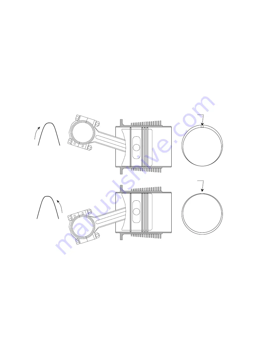
angular direction in the cylinder bore see Figure 20-11,"Ring Positioning." First insure that
the piston and piston rings are centered. This can be accomplished by reducing regulator
pressure to 20 pounds per square inch and working piston through top dead center several
times bringing the piston to top dead center in the normal direction of engine rotation.
Adjust regulated pressure to 80 pounds per square inch and determine amount of loss. If
the gauge reading is higher than the previously determined master orifice calibrated
reading, proceed to next cylinder to be tested.
NOTE. . . Piston ring rotation within the ring land is a normal design characteristic. As
illustrated in Figure 20-11, "Ring Positioning," the compression ring location may have a
direct bearing on the dynamic seal pressure check. Therefore, complete the test in the
opposite direction if readings are below prescribed limits.
FIGURE 20-11. RING POSITIONING
11. If recheck of cylinder pressure gauge reading indication remains below allowable loss,
engine may be run up to operating temperature and rechecked prior to cylinder being
removed and repaired. Rework of cylinders must be accomplished in accordance with
"Cylinder Assembly Repair And Replacement" in the L/TSIO-360 Series Overhaul
Manual, Form X30596A.
TOP COMPRESSION
RING GAP
T.D.C.
DIRECTION
OF
MOVEMENT
T.D.C.
DIRECTION
OF
MOVEMENT
TOP COMPRESSION
RING GAP
Summary of Contents for TSIO-360-RB
Page 11: ...1 5 FIGURE 1 1 Engine Description L TSIO 360 RB ...
Page 12: ...1 6 FIGURE 1 2 ENGINE DESCRIPTION L TSIO 360 RB Cont d ...
Page 13: ...1 7 FIGURE 1 2 ENGINE DESCRIPTION L TSIO 360 RB Cont d ...
Page 14: ...1 8 FIGURE 1 2 ENGINE DESCRIPTION L TSIO 360 RB Cont d ...
Page 15: ...1 9 FIGURE 1 2 ENGINE DESCRIPTION L TSIO 360 RB Cont d ...
Page 25: ...3 1 CHAPTER 3 SEALANTS AND LUBRICANTS Sealants Lubricants 3 2 ...
Page 32: ...4 2 INTENTIONALLY LEFT BLANK ...
Page 54: ...6 2 INTENTIONALLY LEFT BLANK ...
Page 58: ...6 6 FIGURE 6 1 INSTALLATION DRAWING ...
Page 59: ...6 7 FIGURE 6 1 INSTALLATION DRAWING cont d ...
Page 60: ...6 8 FIGURE 6 1 INSTALLATION DRAWING cont d ...
Page 61: ...6 9 FIGURE 6 1 INSTALLATION DRAWING cont d ...
Page 64: ...6 12 INTENTIONALLY LEFT BLANK ...
Page 70: ...7 6 INTENTIONALLY LEFT BLANK ...
Page 82: ...10 2 INTENTIONALLY LEFT BLANK ...
Page 85: ...11 3 FIGURE 11 1 INDUCTION AND EXHAUST SYSTEM ...
Page 94: ...11 12 INTENTIONALLY LEFT BLANK ...
Page 110: ...12 16 INTENTIONALLY LEFT BLANK ...
Page 124: ...14 4 INTENTIONALLY LEFT BLANK ...
Page 128: ...15 4 INTENTIONALLY LEFT BLANK ...
Page 132: ...16 4 INTENTIONALLY LEFT BLANK ...
Page 139: ...17 7 FIGURE 17 4 STARTER ADAPTER FITS LIMITS ...
Page 140: ...17 8 INTENTIONALLY LEFT BLANK ...
Page 143: ...18 3 FIGURE 18 1 ACCESSORY CASE DESCRIPTION ...
Page 147: ...19 3 FIGURE 19 1 LUBRICATION SYSTEM SCHEMATIC ...
Page 149: ...19 5 ACCESSORY CASE INTERNAL VIEW TSIO 360 FIGURE 19 2 OIL PUMP DESCRIPTION TSIO 360 ...
Page 150: ...19 6 ACCESSORY CASE INTERNAL VIEW LTSIO 360 FIGURE 19 3 OIL PUMP DESCRIPTION LTSIO 360 ...
Page 158: ...19 14 INTENTIONALLY LEFT BLANK ...
Page 181: ...21 3 FIGURE 21 1 CRANKCASE DESCRIPTION ...
Page 186: ...21 8 INTENTIONALLY LEFT BLANK ...
Page 194: ...22 8 INTENTIONALLY LEFT BLANK ...
Page 203: ...23 9 FIGURE 23 6 CONSTANT SPEED SEA LEVEL PERFORMANCE CURVE ...
Page 204: ...23 10 FIGURE 23 7 FUEL FLOW VS METERED FUEL PRESSURE ...
Page 205: ...23 11 FIGURE 23 8 FUEL FLOW VS BRAKE HORSEPOWER ...


