20-16
Cylinder Baffling
- Refer to the airframe manufacturer's instructions.
Before any repair procedures are performed after cleaning, the cylinder and it's related
components must be visually, fluorescent penetrant and magnetic particle Inspected as
applicable in accordance with the L/TSIO-360 Series Overhaul Manual, Form X30596A.
CAUTION. . . When performing dimensional inspection the following "Service Limits" may
be used. However, they are intended as a guide for performing maintenance of the engine
prior to major overhaul. Parts with dimensions or fits that exceed service limits must not be
re-used. Parts with values up to and including service limits may be re-used. Judgement
should be exercised considering the PROXIMITY of the engine to its recommended
overhaul time. Service limits must NOT be used when overhauling an engine. See the
current L/TSIO-360 Series Overhaul Manual for minimum fits and limits.
If the cylinder and it's components meet the required visual, fluorescent penetrant and
magnetic particle inspections, the cylinder and its components must be dimensionally
inspected.
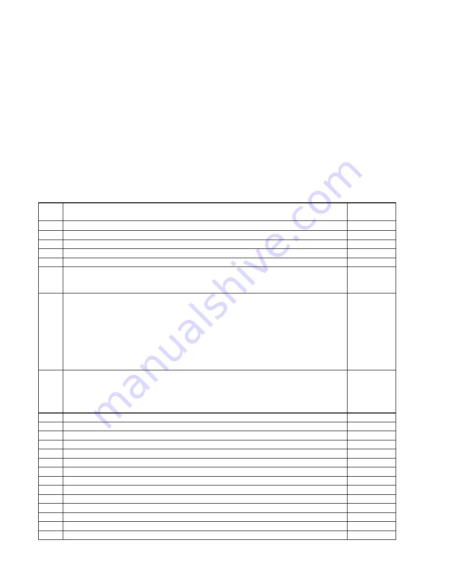
CYLINDER ASSEMBLY SERVICE LIMITS
Ref.
No.
Description
Servicable
Limit Max.
CYLINDER AND HEAD ASSEMBLY
1
|
Cylinder bore (lower 4 1/4" of barrel) ................................................. Diameter:
See Note
|
2
|
Cylinder bore choke at (5.75 from open end of barrel) ...........................Taper:
See Note
|
3
Cylinder bore out-of-round ................................................................................ :
0.0020
4
{ |
Cylinder bore ..................................................................... Allowable Oversize:
See Note
|
5
Cylinder bore surface roughness (Nitride Barrels)
using 180 grit stone,, cross hatch ............................................................Angle:
Microfinish (measured in direction of piston travel)................................... RMS:
22° - 32
°
25
5
Cylinder bore surface roughness (Channeled Chrome)
using 180 grit stone, cross hatch .............................................................Angle:
Finish all area within ring travel. Must show evidence of contact with honing
stone. Partially honed areas shall not exceed 10% of bore surface and no
area shall exceed one inch in any direction.
Finish - pitting is undesirable if present,, it is subject to the following limits:
Pits (No more than two pits in any 1/4 inch Diameter circle)
Not more than 25 pits of any one size in entire cylinder bore is acceptable.
Pit Size................................................................................................ Diameter:
22° - 32°
.031
5
Cylinder bore surface roughness (Cermicrome®)
Finish - pitting is undesirable if present,, it is subject to the following limits:
Pits (No more than two pits in any 1/4 inch Diameter circle)
Not more than 25 pits of any one size in entire cylinder bore is acceptable.
Pit Size................................................................................................ Diameter:
.031
6
Cylinder barrel in crankcase............................................................... Diameter:
0.0110L
7
Intake valve seat insert in cylinder head ............................................ Diameter:
0.0055T
8
Intake valve guide in cylinder head .................................................... Diameter:
0.0010T
9
Exhaust valve guide in cylinder head ................................................. Diameter:
0.0010T
10
Exhaust valve seat insert in cylinder head ......................................... Diameter:
0.0070T
11
Intake valve seat.......................................................................................Width:
See Note
~
12
Exhaust valve seat ...................................................................................Width:
See Note
~
Exhaust valve seat-to-valve guide axis ....................................................Angle:
45° - 30'
Intake valve seat-to-valve guide axis .......................................................Angle:
60° - 30'
ROCKER ARMS AND SHAFTS
13
Rocker shaft in rocker arm bearing .................................................... Diameter:
0.0060L
14
Rocker arm bushing (inside) ........................................... Finish Bore Diameter:
0.5955
15
Rocker Arm............................................................................... Side Clearance:
0.0150
16
Rocker arm to roto-coil ......................................................................Clearance:
0.020
Summary of Contents for TSIO-360-RB
Page 11: ...1 5 FIGURE 1 1 Engine Description L TSIO 360 RB ...
Page 12: ...1 6 FIGURE 1 2 ENGINE DESCRIPTION L TSIO 360 RB Cont d ...
Page 13: ...1 7 FIGURE 1 2 ENGINE DESCRIPTION L TSIO 360 RB Cont d ...
Page 14: ...1 8 FIGURE 1 2 ENGINE DESCRIPTION L TSIO 360 RB Cont d ...
Page 15: ...1 9 FIGURE 1 2 ENGINE DESCRIPTION L TSIO 360 RB Cont d ...
Page 25: ...3 1 CHAPTER 3 SEALANTS AND LUBRICANTS Sealants Lubricants 3 2 ...
Page 32: ...4 2 INTENTIONALLY LEFT BLANK ...
Page 54: ...6 2 INTENTIONALLY LEFT BLANK ...
Page 58: ...6 6 FIGURE 6 1 INSTALLATION DRAWING ...
Page 59: ...6 7 FIGURE 6 1 INSTALLATION DRAWING cont d ...
Page 60: ...6 8 FIGURE 6 1 INSTALLATION DRAWING cont d ...
Page 61: ...6 9 FIGURE 6 1 INSTALLATION DRAWING cont d ...
Page 64: ...6 12 INTENTIONALLY LEFT BLANK ...
Page 70: ...7 6 INTENTIONALLY LEFT BLANK ...
Page 82: ...10 2 INTENTIONALLY LEFT BLANK ...
Page 85: ...11 3 FIGURE 11 1 INDUCTION AND EXHAUST SYSTEM ...
Page 94: ...11 12 INTENTIONALLY LEFT BLANK ...
Page 110: ...12 16 INTENTIONALLY LEFT BLANK ...
Page 124: ...14 4 INTENTIONALLY LEFT BLANK ...
Page 128: ...15 4 INTENTIONALLY LEFT BLANK ...
Page 132: ...16 4 INTENTIONALLY LEFT BLANK ...
Page 139: ...17 7 FIGURE 17 4 STARTER ADAPTER FITS LIMITS ...
Page 140: ...17 8 INTENTIONALLY LEFT BLANK ...
Page 143: ...18 3 FIGURE 18 1 ACCESSORY CASE DESCRIPTION ...
Page 147: ...19 3 FIGURE 19 1 LUBRICATION SYSTEM SCHEMATIC ...
Page 149: ...19 5 ACCESSORY CASE INTERNAL VIEW TSIO 360 FIGURE 19 2 OIL PUMP DESCRIPTION TSIO 360 ...
Page 150: ...19 6 ACCESSORY CASE INTERNAL VIEW LTSIO 360 FIGURE 19 3 OIL PUMP DESCRIPTION LTSIO 360 ...
Page 158: ...19 14 INTENTIONALLY LEFT BLANK ...
Page 181: ...21 3 FIGURE 21 1 CRANKCASE DESCRIPTION ...
Page 186: ...21 8 INTENTIONALLY LEFT BLANK ...
Page 194: ...22 8 INTENTIONALLY LEFT BLANK ...
Page 203: ...23 9 FIGURE 23 6 CONSTANT SPEED SEA LEVEL PERFORMANCE CURVE ...
Page 204: ...23 10 FIGURE 23 7 FUEL FLOW VS METERED FUEL PRESSURE ...
Page 205: ...23 11 FIGURE 23 8 FUEL FLOW VS BRAKE HORSEPOWER ...


