12-11
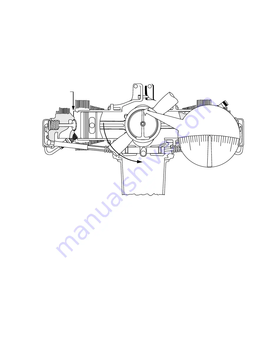
8. Remove the top dead center locator from the number 1 cylinder and find the
compression stroke on the number 1 cylinder by placing a finger over the spark plug
hole as the crankshaft is rotated. Continue rotating crankshaft on the compression
stroke until the 0° mark is under the pointer. On engines equipped with impulse
couplings, continue turning the crankshaft in the normal direction of rotation until each
impulse coupling trips. Couplings may trip a few degrees on either side of top dead
center. If one or both impulse couplings trip after top dead center, turn the propeller
back to a few degrees before top dead center and approach the top dead center position
from the normal direction of rotation.
POSITIVE DEAD CENTER
LOCATOR REMOVED.
# 1 CYLINDER
NOTE: THE PROTRACTOR/TIMING INDICATOR
SHOWN IS USED WITH THE PROPELLER AND
SPINNER INSTALLED.
NORMAL DIRECTION
OF ROTATION.
0
o
TDC POSITION.
350
TDC
10
FIGURE 12-5. TIMING POSITION STEP 4
9. To check either the magneto timing or to time the magneto to the engine, move the
propeller in the opposite direction of normal rotation past the specified magneto timing
setting and then back in the direction of normal rotation until the desired setting before
top dead center is under the pointer to remove the gear backlash. Disconnect the
ground switch leads from the magnetos. Place a Bendix 11-851 timing light or
equivalent on the engine and connect the right lead to the right magneto ground terminal
and connect the left lead to the left magneto ground terminal. Connect the timing light
ground lead to a suitable ground such as a bolt or stud.
With the crankshaft in the correct timing position, turn the crankshaft a few degrees
counterclockwise, then clockwise until the timing pointer is approaching the correct
degree position. As the pointer aligns with the specified timing position, both timing
lights must indicate that both magneto points are breaking within the specified timing
tolerance.
If the magnetos are not timed to the engine within the required specification, the
magneto(s) must be removed from the engine and inspected and repaired in
accordance with the magneto manufacturer's instructions and specifications
Summary of Contents for TSIO-360-RB
Page 11: ...1 5 FIGURE 1 1 Engine Description L TSIO 360 RB ...
Page 12: ...1 6 FIGURE 1 2 ENGINE DESCRIPTION L TSIO 360 RB Cont d ...
Page 13: ...1 7 FIGURE 1 2 ENGINE DESCRIPTION L TSIO 360 RB Cont d ...
Page 14: ...1 8 FIGURE 1 2 ENGINE DESCRIPTION L TSIO 360 RB Cont d ...
Page 15: ...1 9 FIGURE 1 2 ENGINE DESCRIPTION L TSIO 360 RB Cont d ...
Page 25: ...3 1 CHAPTER 3 SEALANTS AND LUBRICANTS Sealants Lubricants 3 2 ...
Page 32: ...4 2 INTENTIONALLY LEFT BLANK ...
Page 54: ...6 2 INTENTIONALLY LEFT BLANK ...
Page 58: ...6 6 FIGURE 6 1 INSTALLATION DRAWING ...
Page 59: ...6 7 FIGURE 6 1 INSTALLATION DRAWING cont d ...
Page 60: ...6 8 FIGURE 6 1 INSTALLATION DRAWING cont d ...
Page 61: ...6 9 FIGURE 6 1 INSTALLATION DRAWING cont d ...
Page 64: ...6 12 INTENTIONALLY LEFT BLANK ...
Page 70: ...7 6 INTENTIONALLY LEFT BLANK ...
Page 82: ...10 2 INTENTIONALLY LEFT BLANK ...
Page 85: ...11 3 FIGURE 11 1 INDUCTION AND EXHAUST SYSTEM ...
Page 94: ...11 12 INTENTIONALLY LEFT BLANK ...
Page 110: ...12 16 INTENTIONALLY LEFT BLANK ...
Page 124: ...14 4 INTENTIONALLY LEFT BLANK ...
Page 128: ...15 4 INTENTIONALLY LEFT BLANK ...
Page 132: ...16 4 INTENTIONALLY LEFT BLANK ...
Page 139: ...17 7 FIGURE 17 4 STARTER ADAPTER FITS LIMITS ...
Page 140: ...17 8 INTENTIONALLY LEFT BLANK ...
Page 143: ...18 3 FIGURE 18 1 ACCESSORY CASE DESCRIPTION ...
Page 147: ...19 3 FIGURE 19 1 LUBRICATION SYSTEM SCHEMATIC ...
Page 149: ...19 5 ACCESSORY CASE INTERNAL VIEW TSIO 360 FIGURE 19 2 OIL PUMP DESCRIPTION TSIO 360 ...
Page 150: ...19 6 ACCESSORY CASE INTERNAL VIEW LTSIO 360 FIGURE 19 3 OIL PUMP DESCRIPTION LTSIO 360 ...
Page 158: ...19 14 INTENTIONALLY LEFT BLANK ...
Page 181: ...21 3 FIGURE 21 1 CRANKCASE DESCRIPTION ...
Page 186: ...21 8 INTENTIONALLY LEFT BLANK ...
Page 194: ...22 8 INTENTIONALLY LEFT BLANK ...
Page 203: ...23 9 FIGURE 23 6 CONSTANT SPEED SEA LEVEL PERFORMANCE CURVE ...
Page 204: ...23 10 FIGURE 23 7 FUEL FLOW VS METERED FUEL PRESSURE ...
Page 205: ...23 11 FIGURE 23 8 FUEL FLOW VS BRAKE HORSEPOWER ...


