


SierraNet
M408
User
Manual
41
Application
Menu
Options
Teledyne
LeCroy
2.5.3
Analysis
The
Analysis
menu
has
the
following
options
to
view
trace
files
and
specify
SCSI
decoding
assignments:
Decoding
Assignments
Spreadsheet
View
Frame
Inspector
View
Traffic
Summary
View
Data
View
Trace
Information
Figure 2.8: Analysis Menu.
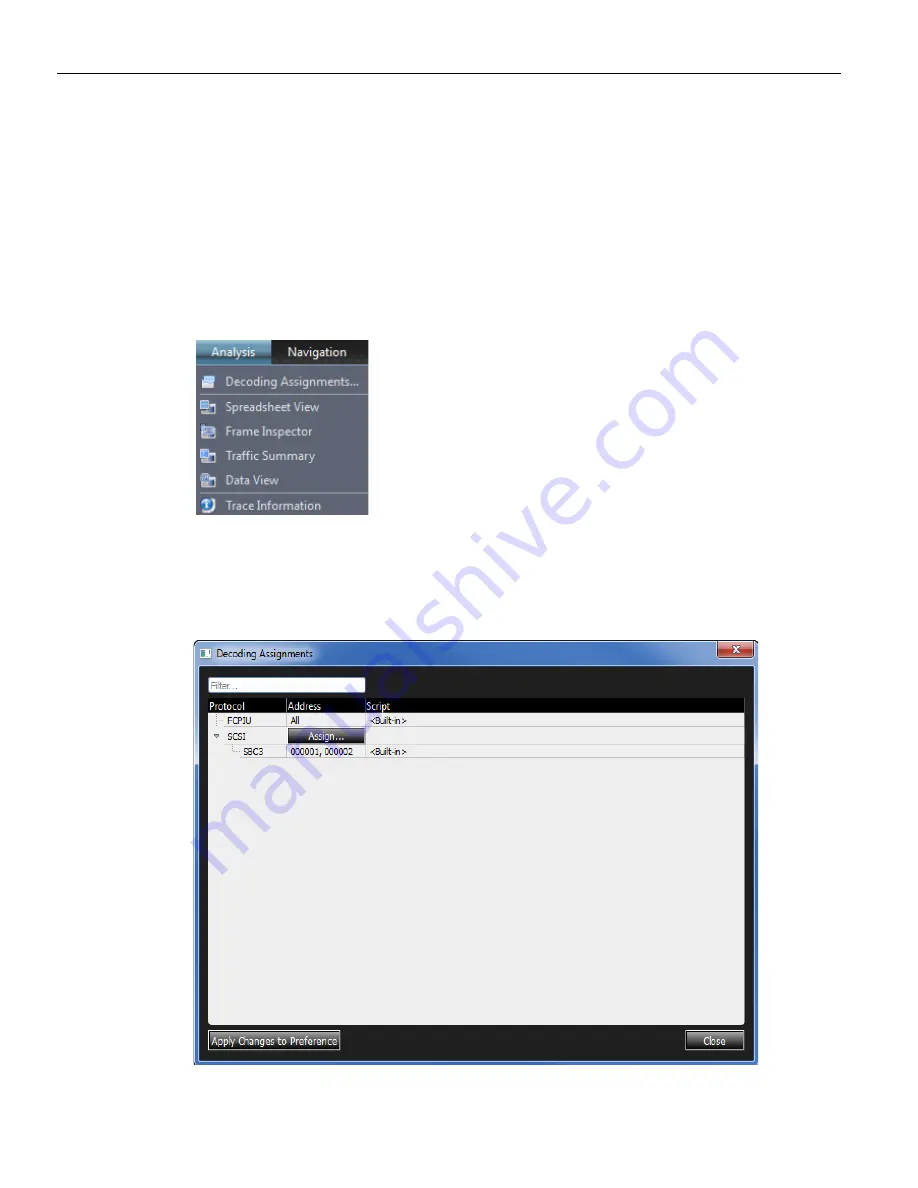
Decoding Assignments
Click
on
Analysis
and
select
Decoding
Assignments
to
display
the
Decoding
Assignments
dialog.
Figure 2.9: Decoding Assignments Dialog.
Summary of Contents for SierraNet M408
Page 1: ...SierraNet M408 User Manual Software Version 1 70 Generated December 15 2014 09 58 ...
Page 8: ...Teledyne LeCroy Contents viii SierraNet M408 User Manual ...
Page 40: ...Teledyne LeCroy CrossSync Control Panel 32 SierraNet M408 User Manual ...
Page 120: ...Teledyne LeCroy Advanced Mode User Defined 112 SierraNet M408 User Manual ...
Page 224: ...Teledyne LeCroy Running Scenarios 216 SierraNet M408 Protocol Analyzer User Manual ...
Page 242: ...Teledyne LeCroy 234 SierraNet M408 User Manual ...
Page 244: ...Teledyne LeCroy 236 SierraNet M408User Manual ...