


Maintenance, Service, and Repair
Brakes
Page 13
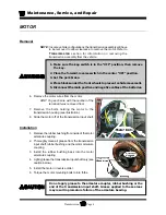
1. Make sure the key-switch is in the “OFF” position, then remove
the key.
2. Place the forward-reverse switch in the center “OFF” position.
3. Set the park brake.
4. Place blocks under the front wheels to prevent vehicle movement.
5. Disconnect the main positive and negative cables at the batteries.
REPAIR THE BRAKE BODY
6. Remove the brake body from the vehicle.
NOTE: Refer to
Replace the Brake Body
Assembly (front or rear)
section for
information on removing the brake body.
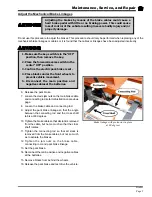
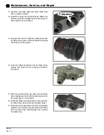
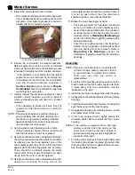
7. Pull the pistons out of the brake body.
8. Remove the piston rubber boot.
9. Remove the piston o-ring from inside of the brake
body.
10. Inspect and replace parts as required.
Hydraulic brake system components must be kept clean. Make sure your
work area is free from dirt and debris and will contain any brake fluid spills.
Any debris or contaminates left in the brake system could lead to brake failure
and result in property damage and/or severe bodily injury.
Do not ingest brake fluid or allow contact with skin or eyes. Always wear
protective clothing and a face shield when working with or around brake
fluid.
SKIN CONTACT
Flush area immediately with water for several minutes. If a rash or skin
irritation develops, get medical attention immediately.
EYE CONTACT
Immediately flush the eye with water for 15 minutes and call physician.
INGESTION
Get medical attention immediately.
The pistons are very fragile. If the piston is
damaged it must be replaced. Failure to
replace a damaged piston could lead to
brake failure and result in property damage
and/or severe bodily injury.
Summary of Contents for B 1-50
Page 2: ......
Page 6: ...TAYLOR DUNN ...
Page 14: ...Model B 1 00 ...
Page 30: ...TAYLOR DUNN ...
Page 36: ...TAYLOR DUNN ...
Page 52: ...TAYLOR DUNN ...
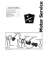
Page 66: ...Maintenance Service and Repair Steering Page 14 Exploded View of Steering Gear ...
Page 90: ...TAYLOR DUNN ...
Page 124: ...TAYLOR DUNN ...
Page 130: ...TAYLOR DUNN ...
Page 161: ...Wire Diagrams ...
Page 194: ...Illustrated Parts PARTS PAGE 10 Front Suspension 4 3 2 1 5 10 6 8 9 7 11 12 ...
Page 202: ...Illustrated Parts PARTS PAGE 18 Motor 2 3 5 6 4 7 8 1 9 10 Armature 9 ...
Page 206: ...Illustrated Parts PARTS PAGE 22 Wheels and Tires Ref wheel hub 1 2 5 assembly 4 3 6 7 8 9 ...
Page 208: ...Illustrated Parts PARTS PAGE 24 Instrument Panel dash ...
Page 217: ...Illustrated Parts PARTS PAGE 33 This page intentionaly left blank ...
Page 220: ...Illustrated Parts PARTS PAGE 36 Seat Cushions Deck and Lights B 1 50 ...
Page 222: ...Illustrated Parts PARTS PAGE 38 Seat Cushions Deck and Lights MX 1600 ...
Page 224: ...Illustrated Parts PARTS PAGE 40 Decals B 1 50 VIEW FROM INSIDE OF COWL 1 2 3 4 5 6 7 8 9 ...
Page 230: ...Illustrated Parts PARTS PAGE 46 Stake Sides B 1 50 1 2 3 4 5 6 7 8 ...


