


Maintenance, Service, and Repair
Transmission
Page 12
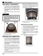
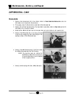
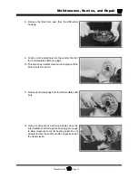
13. Remove the intermediate bearing with an ID bearing
puller.
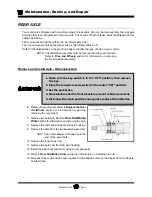
14. While supporting the shaft and gear assembly,
repeat steps #12 and #13 for the opposite side
bearing and remove the intermediate shaft from
the housing.
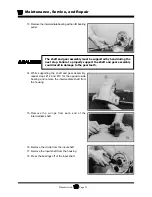
15. Remove the o-rings from each end of the
intermediate shaft.
16. Remove the circlip from the input shaft.
17. Remove the input shaft from the housing.
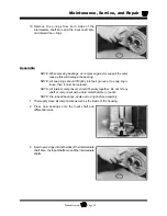
18. Press the bearings off of the input shaft.
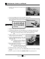
The shaft and gear assembly must be supported by hand during the
next step. Failure to properly support the shaft and gear assembly
could result in damage to the gear teeth.
Summary of Contents for B 1-50
Page 2: ......
Page 6: ...TAYLOR DUNN ...
Page 14: ...Model B 1 00 ...
Page 30: ...TAYLOR DUNN ...
Page 36: ...TAYLOR DUNN ...
Page 52: ...TAYLOR DUNN ...
Page 66: ...Maintenance Service and Repair Steering Page 14 Exploded View of Steering Gear ...
Page 90: ...TAYLOR DUNN ...
Page 124: ...TAYLOR DUNN ...
Page 130: ...TAYLOR DUNN ...
Page 161: ...Wire Diagrams ...
Page 194: ...Illustrated Parts PARTS PAGE 10 Front Suspension 4 3 2 1 5 10 6 8 9 7 11 12 ...
Page 202: ...Illustrated Parts PARTS PAGE 18 Motor 2 3 5 6 4 7 8 1 9 10 Armature 9 ...
Page 206: ...Illustrated Parts PARTS PAGE 22 Wheels and Tires Ref wheel hub 1 2 5 assembly 4 3 6 7 8 9 ...
Page 208: ...Illustrated Parts PARTS PAGE 24 Instrument Panel dash ...
Page 217: ...Illustrated Parts PARTS PAGE 33 This page intentionaly left blank ...
Page 220: ...Illustrated Parts PARTS PAGE 36 Seat Cushions Deck and Lights B 1 50 ...
Page 222: ...Illustrated Parts PARTS PAGE 38 Seat Cushions Deck and Lights MX 1600 ...
Page 224: ...Illustrated Parts PARTS PAGE 40 Decals B 1 50 VIEW FROM INSIDE OF COWL 1 2 3 4 5 6 7 8 9 ...
Page 230: ...Illustrated Parts PARTS PAGE 46 Stake Sides B 1 50 1 2 3 4 5 6 7 8 ...


