


Curtis PMC Troubleshooting
Page 21
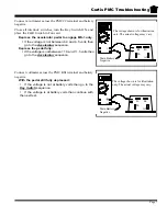
Connect a volt meter across the PMC B+ and PMC
M- terminals.
Turn the key-switch on, close all interlock
switches (if equipped), depress the
accelerator pedal to engage the first micro
switch only (creep speed), then perform the
following tests:
•
The meter reading should not be equal to
the battery voltage.
•
If you have full battery voltage then the
PMC control is shorted and must be
replaced. Stop trouble shooting here and
repair the problem. When the repair is
completed, completely retest the vehicle
before lowering the drive wheels to the
ground, otherwise continue with the next
test.
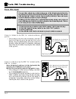
If the voltage at pin #2 is correct and the voltage at ‘M-’ is correct, then there is a short in the
harness between the wire connected to the PMC ‘M-’ and main battery negative. Stop trouble
shooting here and repair the problem. When the repair is completed, completely retest the
vehicle before lowering the drive wheels to the ground.
B-
M-
A2
B+
#2
KSI
_
+
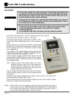
The voltage shown is for illustration
only. The actual voltage may vary.
STOP
Stop, do not continue. If you reached this point without a solution, then you may have an
unanticipated problem or have made an error during testing. It is important to review the
trouble shooting steps that have led to this point. The tests may need to be repeated.
Summary of Contents for B 1-50
Page 2: ......
Page 6: ...TAYLOR DUNN ...
Page 14: ...Model B 1 00 ...
Page 30: ...TAYLOR DUNN ...
Page 36: ...TAYLOR DUNN ...
Page 52: ...TAYLOR DUNN ...
Page 66: ...Maintenance Service and Repair Steering Page 14 Exploded View of Steering Gear ...
Page 90: ...TAYLOR DUNN ...
Page 124: ...TAYLOR DUNN ...
Page 130: ...TAYLOR DUNN ...
Page 161: ...Wire Diagrams ...
Page 194: ...Illustrated Parts PARTS PAGE 10 Front Suspension 4 3 2 1 5 10 6 8 9 7 11 12 ...
Page 202: ...Illustrated Parts PARTS PAGE 18 Motor 2 3 5 6 4 7 8 1 9 10 Armature 9 ...
Page 206: ...Illustrated Parts PARTS PAGE 22 Wheels and Tires Ref wheel hub 1 2 5 assembly 4 3 6 7 8 9 ...
Page 208: ...Illustrated Parts PARTS PAGE 24 Instrument Panel dash ...
Page 217: ...Illustrated Parts PARTS PAGE 33 This page intentionaly left blank ...
Page 220: ...Illustrated Parts PARTS PAGE 36 Seat Cushions Deck and Lights B 1 50 ...
Page 222: ...Illustrated Parts PARTS PAGE 38 Seat Cushions Deck and Lights MX 1600 ...
Page 224: ...Illustrated Parts PARTS PAGE 40 Decals B 1 50 VIEW FROM INSIDE OF COWL 1 2 3 4 5 6 7 8 9 ...
Page 230: ...Illustrated Parts PARTS PAGE 46 Stake Sides B 1 50 1 2 3 4 5 6 7 8 ...


