


Maintenance, Service, and Repair
Brakes
Page 6
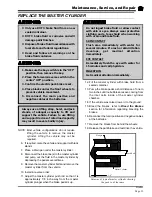
ADJUST THE PARKING BRAKE
Wheel Park Brake (hydraulic drum)
NOTE: Hydraulic brakes are optional. The service
brake must be properly adjusted before
attempting to adjust the parking brake. Refer
to
Adjust the Service Brakes
for
information regarding adjusting the service
brakes.
6. Release the park brake.
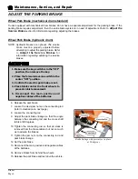
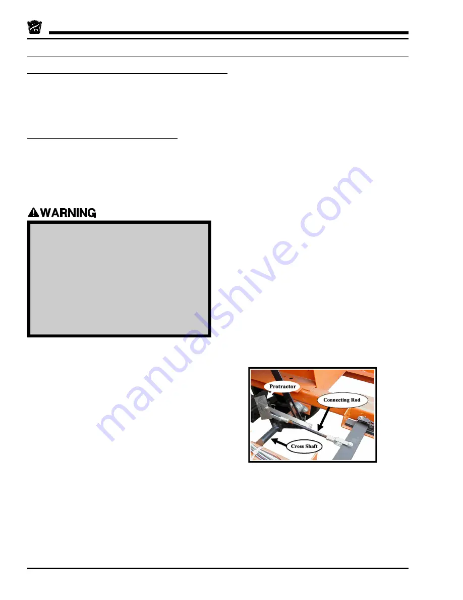
7. Loosen the clevis jam nuts on the connecting rod
(refer to illustration on next page).
8. Loosen the connecting rod.
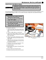
9. Adjust the park brake linkage so that the angle
between the connecting rod and the cross shaft
tab is at 60 degrees.
10. Tighten the connecting rod so that all slack is
removed from the brake cables, but not so much
as to actuate the brakes.
11. Tighten the jam nuts on the connecting rod and
park brake linkage.
12. Set the park brake.
13. Reconnect the main positive and negative cables
at the batteries.
14. Remove blocks from behind the wheels.
15. Release the park brake and test drive the vehicle.
1. Make sure the key-switch is in the “OFF”
position, then remove the key.
2. Place the forward-reverse switch in the
center “OFF” position.
3. Confirm the electric park brake is set.
4. Place blocks under the front wheels to
prevent vehicle movement.
5. Disconnect the main positive and
negative cables at the batteries.
Wheel Park Brake (mechanical drum standard)
Trucks equipped with mechanical drum brakes do not have a separate adjustment for the parking brake. If the
parking brake requires adjustment, then the entire brake system is in need of adjustment. Refer to
Adjust the
Service Brake
section for information regarding adjusting the brakes.
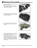
Brake linkage with protractor in place
at 60 degrees
Summary of Contents for B 1-50
Page 2: ......
Page 6: ...TAYLOR DUNN ...
Page 14: ...Model B 1 00 ...
Page 30: ...TAYLOR DUNN ...
Page 36: ...TAYLOR DUNN ...
Page 52: ...TAYLOR DUNN ...
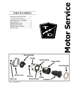
Page 66: ...Maintenance Service and Repair Steering Page 14 Exploded View of Steering Gear ...
Page 90: ...TAYLOR DUNN ...
Page 124: ...TAYLOR DUNN ...
Page 130: ...TAYLOR DUNN ...
Page 161: ...Wire Diagrams ...
Page 194: ...Illustrated Parts PARTS PAGE 10 Front Suspension 4 3 2 1 5 10 6 8 9 7 11 12 ...
Page 202: ...Illustrated Parts PARTS PAGE 18 Motor 2 3 5 6 4 7 8 1 9 10 Armature 9 ...
Page 206: ...Illustrated Parts PARTS PAGE 22 Wheels and Tires Ref wheel hub 1 2 5 assembly 4 3 6 7 8 9 ...
Page 208: ...Illustrated Parts PARTS PAGE 24 Instrument Panel dash ...
Page 217: ...Illustrated Parts PARTS PAGE 33 This page intentionaly left blank ...
Page 220: ...Illustrated Parts PARTS PAGE 36 Seat Cushions Deck and Lights B 1 50 ...
Page 222: ...Illustrated Parts PARTS PAGE 38 Seat Cushions Deck and Lights MX 1600 ...
Page 224: ...Illustrated Parts PARTS PAGE 40 Decals B 1 50 VIEW FROM INSIDE OF COWL 1 2 3 4 5 6 7 8 9 ...
Page 230: ...Illustrated Parts PARTS PAGE 46 Stake Sides B 1 50 1 2 3 4 5 6 7 8 ...


