


Maintenance, Service, and Repair
Steering
Page 13
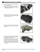
9. Place the upper worm bearing on the worm shaft
and install the worm shaft/ball nut assembly into
the housing being careful not to damage the worm
shaft seal.
10. Install the assembled worm bearing adjuster into
the housing and tighten just enough to remove all
play in the worm shaft.
11. Install, but do not tighten the worm bearing adjuster
lock nut.
12. Rotate the worm shaft to center the ball nut in the
housing.
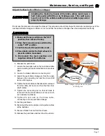
13. Place a new gasket onto the housing and install
the assembled pitman shaft/side cover onto the
housing using two of the three mounting bolts.
14. Pack the steering gear with grease through the open
side cover bolt hole and then install the bolt.
15. Adjust the steering gear.
NOTE: Refer to
Adjust the Steering
gear
section for information regarding
adjusting the steering gear.
16. Once the adjustments are completed, make sure that the locking ring and jam nut are tight.
Summary of Contents for B 1-50
Page 2: ......
Page 6: ...TAYLOR DUNN ...
Page 14: ...Model B 1 00 ...
Page 30: ...TAYLOR DUNN ...
Page 36: ...TAYLOR DUNN ...
Page 52: ...TAYLOR DUNN ...
Page 66: ...Maintenance Service and Repair Steering Page 14 Exploded View of Steering Gear ...
Page 90: ...TAYLOR DUNN ...
Page 124: ...TAYLOR DUNN ...
Page 130: ...TAYLOR DUNN ...
Page 161: ...Wire Diagrams ...
Page 194: ...Illustrated Parts PARTS PAGE 10 Front Suspension 4 3 2 1 5 10 6 8 9 7 11 12 ...
Page 202: ...Illustrated Parts PARTS PAGE 18 Motor 2 3 5 6 4 7 8 1 9 10 Armature 9 ...
Page 206: ...Illustrated Parts PARTS PAGE 22 Wheels and Tires Ref wheel hub 1 2 5 assembly 4 3 6 7 8 9 ...
Page 208: ...Illustrated Parts PARTS PAGE 24 Instrument Panel dash ...
Page 217: ...Illustrated Parts PARTS PAGE 33 This page intentionaly left blank ...
Page 220: ...Illustrated Parts PARTS PAGE 36 Seat Cushions Deck and Lights B 1 50 ...
Page 222: ...Illustrated Parts PARTS PAGE 38 Seat Cushions Deck and Lights MX 1600 ...
Page 224: ...Illustrated Parts PARTS PAGE 40 Decals B 1 50 VIEW FROM INSIDE OF COWL 1 2 3 4 5 6 7 8 9 ...
Page 230: ...Illustrated Parts PARTS PAGE 46 Stake Sides B 1 50 1 2 3 4 5 6 7 8 ...


