

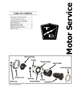

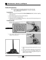

Motor Service
Motor
Page 3
Advanced DC Motors
The enclosed Advanced DC motors must be
disassembled to inspect the motor brushes. Refer to
Motor Inspection
for information regarding
disassembling the motor.
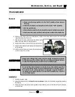
MOTOR REMOVAL AND
INSTALLATION
See the
Transmission
section for information on
removing or installing the motor.
MOTOR INSPECTION
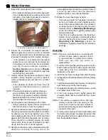
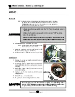
Disassembly
1. Remove the motor from the vehicle. See the
Transmission
section for information on
removing the motor.
2. Remove the housing screws from the rear and/or
front of the motor.
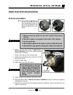
3. Remove the armature retaining screws from the
rear housing (if equipped).
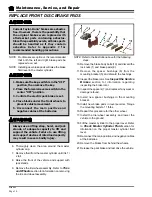
4. If this is an enclosed motor, remove the front
housing end.
5. Pull the armature out of the front end of the motor
housing.
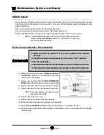
6. Remove the nuts off of all of the terminals in the
rear motor housing.
7. Remove the rear motor housing being careful not
to damage the field coil wires.
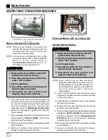
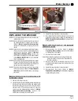
Inspection
1. Measure the length of each motor brush.
• If any one brush is less than or equal to the
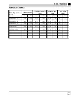
service limit specified in section
Service
Limits
, then all four brushes should be
replaced. Refer to
Replacing the Brushes
section for information regarding replacing the
motor brushes.
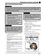
2. Measure the diameter of the commutator.
• If the commutator is less than the minimum
diameter specified in section
Service Limits
,
then the motor must be replaced.
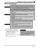
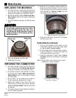
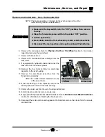
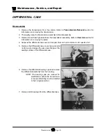
3. Measure the commutator undercut depth in 5-
places around the commutator.
• If any one of the measurements is less than the
minimum undercut depth specified in
Service
Limits
above, then the commutator must be
undercut. Refer to
Repair Commutator
section for information regarding undercutting
the commutator.
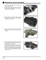
4. Inspect the commutator for grooves.
• If the commutator is groved then it must be
machined on a lathe. Do not machine the
commutator past the minimum diameter
specified in
Service Limits
section. Refer to
Repair Commutator
section for information
regarding machining the commutator.
Insulation
Commutator
Incorrect
Hacksaw blade
Correct
Min. OD
Armature
Undercut
Summary of Contents for B 1-50
Page 2: ......
Page 6: ...TAYLOR DUNN ...
Page 14: ...Model B 1 00 ...
Page 30: ...TAYLOR DUNN ...
Page 36: ...TAYLOR DUNN ...
Page 52: ...TAYLOR DUNN ...
Page 66: ...Maintenance Service and Repair Steering Page 14 Exploded View of Steering Gear ...
Page 90: ...TAYLOR DUNN ...
Page 124: ...TAYLOR DUNN ...
Page 130: ...TAYLOR DUNN ...
Page 161: ...Wire Diagrams ...
Page 194: ...Illustrated Parts PARTS PAGE 10 Front Suspension 4 3 2 1 5 10 6 8 9 7 11 12 ...
Page 202: ...Illustrated Parts PARTS PAGE 18 Motor 2 3 5 6 4 7 8 1 9 10 Armature 9 ...
Page 206: ...Illustrated Parts PARTS PAGE 22 Wheels and Tires Ref wheel hub 1 2 5 assembly 4 3 6 7 8 9 ...
Page 208: ...Illustrated Parts PARTS PAGE 24 Instrument Panel dash ...
Page 217: ...Illustrated Parts PARTS PAGE 33 This page intentionaly left blank ...
Page 220: ...Illustrated Parts PARTS PAGE 36 Seat Cushions Deck and Lights B 1 50 ...
Page 222: ...Illustrated Parts PARTS PAGE 38 Seat Cushions Deck and Lights MX 1600 ...
Page 224: ...Illustrated Parts PARTS PAGE 40 Decals B 1 50 VIEW FROM INSIDE OF COWL 1 2 3 4 5 6 7 8 9 ...
Page 230: ...Illustrated Parts PARTS PAGE 46 Stake Sides B 1 50 1 2 3 4 5 6 7 8 ...


