


Maintenance, Service, and Repair
Steering
Page 10
REPLACE THE STEERING GEAR
6. Remove the steering wheel.
NOTE: Refer to
Replace the Steering Wheel
section for information
regarding removing the steering wheel.
7. Remove the steering shaft.
NOTE: Refer to
Replace the Steering Shaft
section for information
regarding removing the steering shaft.
8. Remove the pitman arm using a pickle fork.
NOTE: On some vehicle configurations it may
be required to remove the drag link
from the pitman arm. Refer to
Replace the Ball Joints
section for
information regarding removing the
ball joint from the pitman arm.
9. Support the steering gear so that it cannot fall out
of the vehicle.
1. Make sure the key-switch is in the “OFF” position, then remove
the key.
2. Place the forward-reverse switch in the center “OFF” position.
3. Set the park brake.
4. Place blocks under the rear wheels to prevent vehicle movement.
5. Disconnect the main positive and negative cables at the batteries.
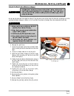
Steering Gear with Pitman Arm
Failure to support the
steering gear will result in
the steering gear falling out
of the vehicle and could
cause property damage and/
or severe bodily injury.
10. Remove the bolts holding the steering gear to the vehicle frame and remove the steering gear
from the vehicle.
11. Install in reverse order. Torque the pitman arm nut to75-100 ft-lbs.
12. Reconnect the main positive and negative cables at the batteries.
13. Remove the blocks from behind the wheels.
14. Release the parking brake and test drive the vehicle.
Summary of Contents for B 1-50
Page 2: ......
Page 6: ...TAYLOR DUNN ...
Page 14: ...Model B 1 00 ...
Page 30: ...TAYLOR DUNN ...
Page 36: ...TAYLOR DUNN ...
Page 52: ...TAYLOR DUNN ...
Page 66: ...Maintenance Service and Repair Steering Page 14 Exploded View of Steering Gear ...
Page 90: ...TAYLOR DUNN ...
Page 124: ...TAYLOR DUNN ...
Page 130: ...TAYLOR DUNN ...
Page 161: ...Wire Diagrams ...
Page 194: ...Illustrated Parts PARTS PAGE 10 Front Suspension 4 3 2 1 5 10 6 8 9 7 11 12 ...
Page 202: ...Illustrated Parts PARTS PAGE 18 Motor 2 3 5 6 4 7 8 1 9 10 Armature 9 ...
Page 206: ...Illustrated Parts PARTS PAGE 22 Wheels and Tires Ref wheel hub 1 2 5 assembly 4 3 6 7 8 9 ...
Page 208: ...Illustrated Parts PARTS PAGE 24 Instrument Panel dash ...
Page 217: ...Illustrated Parts PARTS PAGE 33 This page intentionaly left blank ...
Page 220: ...Illustrated Parts PARTS PAGE 36 Seat Cushions Deck and Lights B 1 50 ...
Page 222: ...Illustrated Parts PARTS PAGE 38 Seat Cushions Deck and Lights MX 1600 ...
Page 224: ...Illustrated Parts PARTS PAGE 40 Decals B 1 50 VIEW FROM INSIDE OF COWL 1 2 3 4 5 6 7 8 9 ...
Page 230: ...Illustrated Parts PARTS PAGE 46 Stake Sides B 1 50 1 2 3 4 5 6 7 8 ...