


Electrical Troubleshooting
Charger Troubleshooting
Page 3
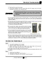
TESTING THE CHARGING CYCLE
In typical installations, the charger will remain on for up to 12 hours depending on the state of charge of the
battery when the charge cycle was started.
A charger could remain on for longer than 12 hours if:
• The charging cycle is interrupted at any time during the charging cycle.
• Defective batteries causing a fluctuating DC voltage that confuses the charger.
• A brownout (drop in AC line voltage) during the charging cycle.
• An electrically noisy charging environment.
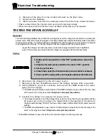
A charger could turn off in less than 12 hours, but still show symptoms of overcharging if:
• The batteries were not discharged to 50% before connecting the charger.
• The electrolyte in the batteries is too high (boil over).
• The electrolyte in the batteries is too low (excessive gassing or sulfur smell).
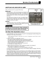
To test the charger to see if it is turning off correctly, monitor the battery
voltage and the electrolyte specific gravity during the charging cycle as
indicated below.
Specific Gravity
Using a hydrometer take the specific gravity reading of several cells, at 1 hour intervals while charging. If
the specific gravity of the electrolyte does not rise for three consecutive readings and the charger does not
shut off, then the charger is running too long.
Battery Voltage
Using an accurate 5-1/2 digit digital voltmeter, monitor the battery voltage during the charging cycle. Take
readings every 30 minutes. If the battery voltage does not increase 0.012 volts in two consecutive readings,
then the charger is running too long.
Summary of Contents for B 1-50
Page 2: ......
Page 6: ...TAYLOR DUNN ...
Page 14: ...Model B 1 00 ...
Page 30: ...TAYLOR DUNN ...
Page 36: ...TAYLOR DUNN ...
Page 52: ...TAYLOR DUNN ...
Page 66: ...Maintenance Service and Repair Steering Page 14 Exploded View of Steering Gear ...
Page 90: ...TAYLOR DUNN ...
Page 124: ...TAYLOR DUNN ...
Page 130: ...TAYLOR DUNN ...
Page 161: ...Wire Diagrams ...
Page 194: ...Illustrated Parts PARTS PAGE 10 Front Suspension 4 3 2 1 5 10 6 8 9 7 11 12 ...
Page 202: ...Illustrated Parts PARTS PAGE 18 Motor 2 3 5 6 4 7 8 1 9 10 Armature 9 ...
Page 206: ...Illustrated Parts PARTS PAGE 22 Wheels and Tires Ref wheel hub 1 2 5 assembly 4 3 6 7 8 9 ...
Page 208: ...Illustrated Parts PARTS PAGE 24 Instrument Panel dash ...
Page 217: ...Illustrated Parts PARTS PAGE 33 This page intentionaly left blank ...
Page 220: ...Illustrated Parts PARTS PAGE 36 Seat Cushions Deck and Lights B 1 50 ...
Page 222: ...Illustrated Parts PARTS PAGE 38 Seat Cushions Deck and Lights MX 1600 ...
Page 224: ...Illustrated Parts PARTS PAGE 40 Decals B 1 50 VIEW FROM INSIDE OF COWL 1 2 3 4 5 6 7 8 9 ...
Page 230: ...Illustrated Parts PARTS PAGE 46 Stake Sides B 1 50 1 2 3 4 5 6 7 8 ...


