
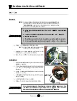


Maintenance, Service, and Repair
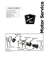
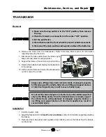
Transmission
Page 5
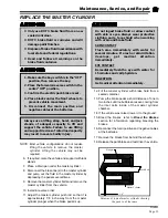
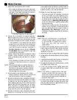
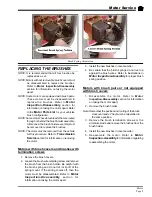
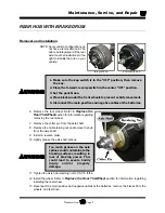
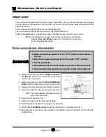
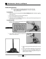
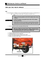
REAR HUB WITH BRAKE DRUM
Removal and Installation
NOTE: Some vehicle configurations do
not have a removable hub. The
hub is an integral part of the rear
axle. See the illustrations to the
right to identify the hub on your
vehicle.
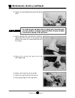
1. Make sure the key-switch is in the “OFF” position, then remove
the key.
2. Place the forward-reverse switch in the center “OFF” position.
3. Set the park brake.
4. Place blocks under the front wheels to prevent vehicle movement.
5. Disconnect the main positive and negative cables at the batteries.
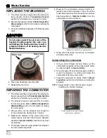
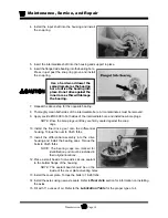
Too much grease on the axle
splines could contaminate the
braking surfaces resulting in
loss of braking power. This
could lead to severe bodily
injury and/or property
damage.
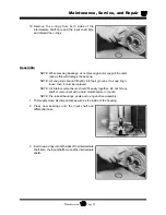
6. Remove the rear wheel. Refer to
Replace the
Rear Tire/Wheel
section for information regarding
removing the rear wheel.
7. Remove the cotter pin from the axle shaft.
8. Remove the hub retaining nut and remove the hub
from the axle shaft.
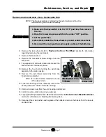
9. Install in reverse order.
10. Lightly grease the axle shaft splines.
11. Tighten the axle hub retaining nut to 95-115 ft-lbs.
12. Install the wheel. Refer to
Replace the Rear Tire/Wheel
section for information regarding
installing the rear wheel.
13. Reconnect the main positive and negative cables at the batteries, remove the blocks from the
wheels, and test drive.
Integral hub
Removable hub
Summary of Contents for B 1-50
Page 2: ......
Page 6: ...TAYLOR DUNN ...
Page 14: ...Model B 1 00 ...
Page 30: ...TAYLOR DUNN ...
Page 36: ...TAYLOR DUNN ...
Page 52: ...TAYLOR DUNN ...
Page 66: ...Maintenance Service and Repair Steering Page 14 Exploded View of Steering Gear ...
Page 90: ...TAYLOR DUNN ...
Page 124: ...TAYLOR DUNN ...
Page 130: ...TAYLOR DUNN ...
Page 161: ...Wire Diagrams ...
Page 194: ...Illustrated Parts PARTS PAGE 10 Front Suspension 4 3 2 1 5 10 6 8 9 7 11 12 ...
Page 202: ...Illustrated Parts PARTS PAGE 18 Motor 2 3 5 6 4 7 8 1 9 10 Armature 9 ...
Page 206: ...Illustrated Parts PARTS PAGE 22 Wheels and Tires Ref wheel hub 1 2 5 assembly 4 3 6 7 8 9 ...
Page 208: ...Illustrated Parts PARTS PAGE 24 Instrument Panel dash ...
Page 217: ...Illustrated Parts PARTS PAGE 33 This page intentionaly left blank ...
Page 220: ...Illustrated Parts PARTS PAGE 36 Seat Cushions Deck and Lights B 1 50 ...
Page 222: ...Illustrated Parts PARTS PAGE 38 Seat Cushions Deck and Lights MX 1600 ...
Page 224: ...Illustrated Parts PARTS PAGE 40 Decals B 1 50 VIEW FROM INSIDE OF COWL 1 2 3 4 5 6 7 8 9 ...
Page 230: ...Illustrated Parts PARTS PAGE 46 Stake Sides B 1 50 1 2 3 4 5 6 7 8 ...


