


Curtis PMC Troubleshooting
Page 26
1. Make sure the key-switch is in the “OFF” position, then remove
the key.
2. Place the forward-reverse switch in the center “OFF” position.
3. Set the park brake.
4. Place blocks under the front wheels to prevent vehicle movement.
5. Disconnect the main positive and negative cables at the batteries.
The rear drive wheels may rotate during some of the following tests.
Block the front wheels, raise the rear drive wheels off the ground,
and support the vehicle with jack stands. Failure to do so may cause
the vehicle to move and cause severe bodily injury and/or property
damage.
Rotating rear drive wheels are a potential hazard. Keep hands, arms,
legs and loose clothing away from the rear drive wheels while
conducting tests. Failure to do so may cause serious bodily injury.
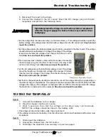
Motor shown for reference
only. Terminal positions on
your motor may not be in the
same location.
S2
A1
A2
S1
_
+
SOLENOIDS
There is a very slight possibility that a failure in the motor could cause these symptoms.
Perform the tests covered in the MOTOR section first. If the motor is OK, continue with the
following tests.
Remove the wires from the ‘S1’ and ‘S2’ terminals on the motor. Remove the wire from the
‘M-’ terminal on the PMC control. Make sure none of these wires can come into electrical contact
with the frame or any other wire.
Reconnect the batteries.
With the key-switch on and the forward and reverse switch in neutral, perform the
following tests:
•
Check continuity from the motor ‘A2’
terminal to the wire that was connected
to the motor ‘S1’ terminal. DO NOT make
this test to the ‘S1” terminal, just the wire.
Refer to Solenoid Figure 1.
If you do not know how to test for continuity,
refer test to a qualified technician.
•
This should be an open circuit, if it reads
as a short, then one of the following has
occurred:
A) The reverse solenoid is shorted.
B) The wire connected to the motor ‘S1’
terminal is shorted to the wire connected
to the motor ‘A2’ terminal.
C) The wire connected to the motor ‘S1’
terminal is shorted to the wire connected to the PMC ‘A2’ terminal.
Summary of Contents for B 1-50
Page 2: ......
Page 6: ...TAYLOR DUNN ...
Page 14: ...Model B 1 00 ...
Page 30: ...TAYLOR DUNN ...
Page 36: ...TAYLOR DUNN ...
Page 52: ...TAYLOR DUNN ...
Page 66: ...Maintenance Service and Repair Steering Page 14 Exploded View of Steering Gear ...
Page 90: ...TAYLOR DUNN ...
Page 124: ...TAYLOR DUNN ...
Page 130: ...TAYLOR DUNN ...
Page 161: ...Wire Diagrams ...
Page 194: ...Illustrated Parts PARTS PAGE 10 Front Suspension 4 3 2 1 5 10 6 8 9 7 11 12 ...
Page 202: ...Illustrated Parts PARTS PAGE 18 Motor 2 3 5 6 4 7 8 1 9 10 Armature 9 ...
Page 206: ...Illustrated Parts PARTS PAGE 22 Wheels and Tires Ref wheel hub 1 2 5 assembly 4 3 6 7 8 9 ...
Page 208: ...Illustrated Parts PARTS PAGE 24 Instrument Panel dash ...
Page 217: ...Illustrated Parts PARTS PAGE 33 This page intentionaly left blank ...
Page 220: ...Illustrated Parts PARTS PAGE 36 Seat Cushions Deck and Lights B 1 50 ...
Page 222: ...Illustrated Parts PARTS PAGE 38 Seat Cushions Deck and Lights MX 1600 ...
Page 224: ...Illustrated Parts PARTS PAGE 40 Decals B 1 50 VIEW FROM INSIDE OF COWL 1 2 3 4 5 6 7 8 9 ...
Page 230: ...Illustrated Parts PARTS PAGE 46 Stake Sides B 1 50 1 2 3 4 5 6 7 8 ...


