


Motor Service
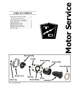
Motor
Page 4
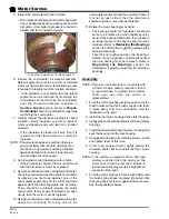
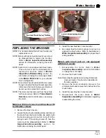
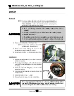
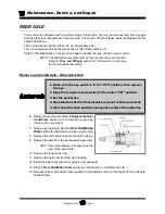
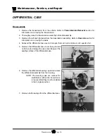
5. Inspect the commutator for burn marks.
• Burn marks and/or raised commutator segments
90 or 180 degrees apart is evidence of a shorted
armature. A tool called a growler is required to
reliably test for a shorted armature.
6. Inspect the commutator for raised segments.
Raised segments could be a result of a stalled
motor or shorted armature. A tool called a growler
is required to reliably test for a shorted armature.
• If the armature is not shorted then the raised
segments can be removed by machining the
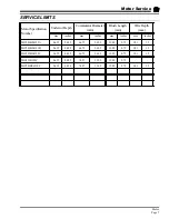
commutator. Do not machine the commutator
past the minimum diameter specified in
Service Limits
section. Refer to
Repair
Commutator
section for information regarding
machining the commutator.
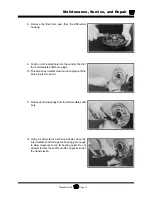
7. Visually inspect the armature windings for burnt
insulation. Burnt insulation is a direct result of
motor overheating and could lead to a shorted
armature.
• If the insulation is cracked or burnt, then it is
recommend that the armature or motor be
replaced.
NOTE: If the armature has been burnt then there is a
good possibility that the field windings may
also be burnt. Symptoms indicating a shorted
field include high motor current, lack of power
and possibly excessive speed.
8. Using a growler, test the armature for shorts.
• If the armature is shorted, then we recommend
that the armature or motor be replaced.
9. Using the continuity function of digital multi meter,
check the continuity around the entire commutator
by placing one test lead against one of the
commutator segments and the other test lead
against all of the other segments one at a time.
There should be continuity around the entire
commutator. If any segment indicates an open
circuit, then the motor must be replaced.
10. Using the continuity function of digital multi meter,
check the continuity from any one of the
commutator segments and the armature frame. If
it is not an open circuit, then the armature is
shorted and the motor must be replaced.
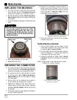
11. Rotate the motor bearing(s) by hand.
• The bearing should not ‘freewheel’ but should
come to a smooth stop when rapidly spun by
hand. If the bearing freewheels, then grease is
no longer present in the bearing and it must be
replaced. Refer to
Replacing the Bearings
section for information regarding replacing the
armature bearings.
• Feel for any roughness when the bearing is
rotated. If any roughness or grinding is noticed
then the bearing must be replaced. Refer to
Replacing the Bearings
section for
information regarding replacing the armature
bearings.
Assembly
NOTE: If this is an enclosed motor on a vehicle with
a Power Traction primary reduction, then it
is recommended to replace the armature
shaft seal any time the motor is
disassembled.
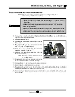
1. Push the motor brushes just far enough out of the
brush holder so that the brush springs hold them
in place away from the commutator. See the
illustration to the right.
2. Install the rear motor housing to the stator housing.
3. Lightly grease the outside diameter of the armature
bearings.
4. Insert the armature through the stator housing and
seat the bearing into the rear housing.
5. If equipped with armature retaining screws, install
and tighten them at this time.
6. If this is an enclosed motor, lightly grease the
armature shaft seal and install the front motor
housing.
NOTE: If the vehicle is equipped with a belt type
primary reduction then the spring on the
motor seal should be removed. Failure to
remove the spring may result in a high pitched
squeal from the seal.
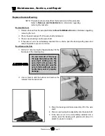
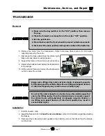
7. Push the motor brushes into the brush holder until
the brush spring snaps into place. Be certain that
the spring does not rest up against the brush wire.
See the illustrations below.
Typical burn mark on a shorted armature
Summary of Contents for B 1-50
Page 2: ......
Page 6: ...TAYLOR DUNN ...
Page 14: ...Model B 1 00 ...
Page 30: ...TAYLOR DUNN ...
Page 36: ...TAYLOR DUNN ...
Page 52: ...TAYLOR DUNN ...
Page 66: ...Maintenance Service and Repair Steering Page 14 Exploded View of Steering Gear ...
Page 90: ...TAYLOR DUNN ...
Page 124: ...TAYLOR DUNN ...
Page 130: ...TAYLOR DUNN ...
Page 161: ...Wire Diagrams ...
Page 194: ...Illustrated Parts PARTS PAGE 10 Front Suspension 4 3 2 1 5 10 6 8 9 7 11 12 ...
Page 202: ...Illustrated Parts PARTS PAGE 18 Motor 2 3 5 6 4 7 8 1 9 10 Armature 9 ...
Page 206: ...Illustrated Parts PARTS PAGE 22 Wheels and Tires Ref wheel hub 1 2 5 assembly 4 3 6 7 8 9 ...
Page 208: ...Illustrated Parts PARTS PAGE 24 Instrument Panel dash ...
Page 217: ...Illustrated Parts PARTS PAGE 33 This page intentionaly left blank ...
Page 220: ...Illustrated Parts PARTS PAGE 36 Seat Cushions Deck and Lights B 1 50 ...
Page 222: ...Illustrated Parts PARTS PAGE 38 Seat Cushions Deck and Lights MX 1600 ...
Page 224: ...Illustrated Parts PARTS PAGE 40 Decals B 1 50 VIEW FROM INSIDE OF COWL 1 2 3 4 5 6 7 8 9 ...
Page 230: ...Illustrated Parts PARTS PAGE 46 Stake Sides B 1 50 1 2 3 4 5 6 7 8 ...


