


Electrical Troubleshooting
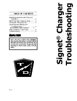
Signet Charger Troubleshooting
Page 6
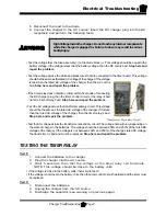
1. Make sure the key-switch is in the “OFF” position, then remove the
key.
2. Place the forward-reverse switch in the center “OFF” position.
3. Set the park brake.
4. Place blocks under the front wheels to prevent vehicle movement.
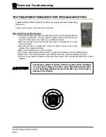
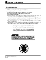
TROUBLESHOOTING
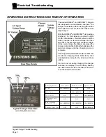
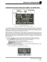
To test charger operation:
Connect a DC volt meter to the main battery positive and negative terminals.
Attach a clamp on DC Ammeter to one of the charger DC output wires.
Plug the charger into an AC outlet.
Wait for charger to start (up to15 seconds), the ammeter should display the DC Amp rating of the charger
(plus or minus 10%) indicating that the charger is on (constant current mode).
The ammeter should continue to display the DC Amp rating of the charger until the battery voltage equals
2.55 VPC. When the battery voltage equals 2.55 VPC the charger will switch to the constant voltage
mode. At this point the charging current will be reduced and will taper off until the batteries are fully
charged.
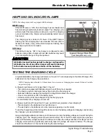
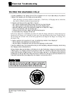
Perform the following if the charger does not turn on:
5. Disconnect the charger from the AC source.
6. Remove the charger end cap where the DC
wires enter.
7. Test the voltage across the Battery Positive
(red) and Battery Negative (black) wires at
the lower left of the charger circuit board.
This voltage should be equal to the battery
voltage. If the voltage is less than the battery
voltage, then the wires to the batteries have
been damaged.
Stop here and repair the
problem.
8. Reinstall the charger end cap where the DC
wires enter.
9. Remove the charger end cap where the AC
wires enter.
10.Test the continuity of all three AC wires from
the circuit board to the AC plug. If you find
an open circuit in any one of the three wires
then the AC cord or plug has been
damaged.
Stop here and repair the problem.
11.Install the charger end cap where the AC
wires enter.
If both the AC and DC tests are good then the charger has failed. There are no internally serviceable
components in the charger. If the charger has failed then it must be replaced.
Summary of Contents for B 1-50
Page 2: ......
Page 6: ...TAYLOR DUNN ...
Page 14: ...Model B 1 00 ...
Page 30: ...TAYLOR DUNN ...
Page 36: ...TAYLOR DUNN ...
Page 52: ...TAYLOR DUNN ...
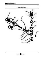
Page 66: ...Maintenance Service and Repair Steering Page 14 Exploded View of Steering Gear ...
Page 90: ...TAYLOR DUNN ...
Page 124: ...TAYLOR DUNN ...
Page 130: ...TAYLOR DUNN ...
Page 161: ...Wire Diagrams ...
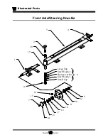
Page 194: ...Illustrated Parts PARTS PAGE 10 Front Suspension 4 3 2 1 5 10 6 8 9 7 11 12 ...
Page 202: ...Illustrated Parts PARTS PAGE 18 Motor 2 3 5 6 4 7 8 1 9 10 Armature 9 ...
Page 206: ...Illustrated Parts PARTS PAGE 22 Wheels and Tires Ref wheel hub 1 2 5 assembly 4 3 6 7 8 9 ...
Page 208: ...Illustrated Parts PARTS PAGE 24 Instrument Panel dash ...
Page 217: ...Illustrated Parts PARTS PAGE 33 This page intentionaly left blank ...
Page 220: ...Illustrated Parts PARTS PAGE 36 Seat Cushions Deck and Lights B 1 50 ...
Page 222: ...Illustrated Parts PARTS PAGE 38 Seat Cushions Deck and Lights MX 1600 ...
Page 224: ...Illustrated Parts PARTS PAGE 40 Decals B 1 50 VIEW FROM INSIDE OF COWL 1 2 3 4 5 6 7 8 9 ...
Page 230: ...Illustrated Parts PARTS PAGE 46 Stake Sides B 1 50 1 2 3 4 5 6 7 8 ...


