


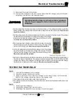


Electrical Troubleshooting
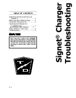
Signet Charger Troubleshooting
Page 2
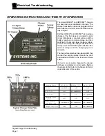
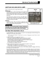
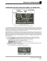
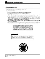
OPERATING INSTRUCTIONS AND THEORY OF OPERATION
The model HB600W
®
and HB1000W
®
chargers
are designed as semiautomatic chargers. The
charger turns itself on when it is plugged into the
wall outlet and turns off when the batteries are
fully charged.
Both the HB600W
®
and HB1000W
®
are two stage
chargers. The first stage is a constant current
mode. It Maintains a constant current until the
battery reaches a terminal voltage and then
switches to the second stage, constant voltage.
At the second stage the charger decreases the
charger current while holding the batteries at the
terminal voltage until the charging cycle is
complete.
The charger faceplate has three status LED’s that
monitor the charging status. Refer to the chart
and illustration below for the function of these
LED’s.
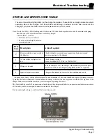
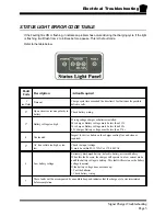
If an error occurs during charging, the charger
will beep, and display an error code by flashing
the status LED’s. Refer to the Status LED error
code table later in this section.
C h a r g ing S ta tus
L e ft ( 5 0 % )
M id d le (7 5 % )
R ight (1 0 0 % )
0 - 5 0 %
F L A S H I N G
O F F
O F F
5 0 % - 7 5 %
O N
F L A S H I N G
O F F
7 5 % - 1 0 0 %
O N
O N
F L A S H I N G
C h a r g ing C y c le
c o m p le te
O N
O N
O N
E rro r, r e fe r to
tro u b le s h o o ting
F L A S H I N G
F L A S H I N G
F L A S H I N G
C h a r g e r T im e O ut
O F F
O F F
F L A S H I N G
Summary of Contents for B 1-50
Page 2: ......
Page 6: ...TAYLOR DUNN ...
Page 14: ...Model B 1 00 ...
Page 30: ...TAYLOR DUNN ...
Page 36: ...TAYLOR DUNN ...
Page 52: ...TAYLOR DUNN ...
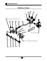
Page 66: ...Maintenance Service and Repair Steering Page 14 Exploded View of Steering Gear ...
Page 90: ...TAYLOR DUNN ...
Page 124: ...TAYLOR DUNN ...
Page 130: ...TAYLOR DUNN ...
Page 161: ...Wire Diagrams ...
Page 194: ...Illustrated Parts PARTS PAGE 10 Front Suspension 4 3 2 1 5 10 6 8 9 7 11 12 ...
Page 202: ...Illustrated Parts PARTS PAGE 18 Motor 2 3 5 6 4 7 8 1 9 10 Armature 9 ...
Page 206: ...Illustrated Parts PARTS PAGE 22 Wheels and Tires Ref wheel hub 1 2 5 assembly 4 3 6 7 8 9 ...
Page 208: ...Illustrated Parts PARTS PAGE 24 Instrument Panel dash ...
Page 217: ...Illustrated Parts PARTS PAGE 33 This page intentionaly left blank ...
Page 220: ...Illustrated Parts PARTS PAGE 36 Seat Cushions Deck and Lights B 1 50 ...
Page 222: ...Illustrated Parts PARTS PAGE 38 Seat Cushions Deck and Lights MX 1600 ...
Page 224: ...Illustrated Parts PARTS PAGE 40 Decals B 1 50 VIEW FROM INSIDE OF COWL 1 2 3 4 5 6 7 8 9 ...
Page 230: ...Illustrated Parts PARTS PAGE 46 Stake Sides B 1 50 1 2 3 4 5 6 7 8 ...


