Page 18
S
,
UNBEAM
Section C (Fuel System)
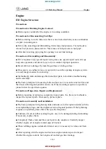
the cylinder is charged with petrol admitted from
the floatchamber through the non-return valve.
The piston is spring-loaded, and Is retained in its
cylinder by a shouldered screw. When the
throttle is opened, the piston is forced down by the
pump linkage, discharging a stream of petrol via an
internal passage through the non-return pump
discharge ball valve and pump discharge nozzle into
the air stream.
The pump discharge nozzle consists of a small die
casting shown in section In the inset of Fig. 13. Fuel
is fed into the nozzle centre and discharged under
ACCELERATOR PUMP
DISCHARGE NOZZLE
the pressure exerted by the fuel pump through a
small calibrated hole into a space In the nozzle.
This space is in communication with the float
chamber air vent hole leading to the outside of the
carburettor. From this space the fuel enters the
main air stream by a larger hole in an emulsified
state.
If the pump discharge ball valve Is not seating
properly, this arrangement assists in preventing
a continuous fuel discharge from the nozzle by
relieving it of the depression in the area of the
venturi.
- -
....
-
ACCELERATOR PUMP
NON-RETURN
BALL VALVE
AIR FLOW
ACCELERATOR PUMP
NON-RETURN VALVE
ACCELERATOR PUMP
PLU.NGER RETURN SPRING
-
FUEL
Fig.
13.
Accelerator pump operating
Summary of Contents for ALPINE I SERIES: APLINE II SERIES
Page 1: ......
Page 189: ...Fis 21 Ball pin heirht checkinr fixture in position Details of items 1 to 4 In Fig 22...
Page 208: ...Fla 3 Exploded view of rear axle Hypoid Bevel Drive...
Page 220: ...Page 16 WSM 12 f Section G Rear Axle 0 QQ I I I I I t 0 ii 8 ts t 0 Cl 2 i J...
Page 247: ...Page6 WSM 124 Section J Steering N Iii it...
Page 299: ...Page 40 3 6 7 8 Fis 22 Se rvo unit exploded view Sect WSM 124 ion K Brakes 18 419 GZo 21...
Page 413: ..._ PRINTED IN ENGLAND 9Y WREN PRINTING CQ LTD LONDON...