WSM.124
Section B (Engine)
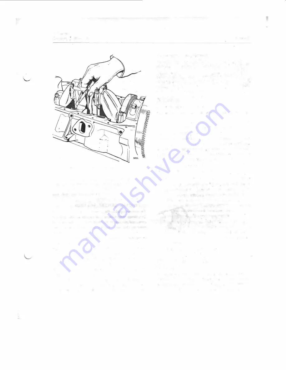
Fig. 49.
Checking crankshaft
end
float
under "Crankshaft". Similar dimen�loned oversize
main and big end bearings can also be obtained.
Crankshaft-To refit
Check that oilways are clear.
Place crankshaft in position, checking that top
halves of the main bearings and thrust washers
(centre) are correctly fitted Into the crankcase.
Thrust Is taken by two halfwashers fitted to the side
faces of the centre main· bearing In the cylinder
block.
Fit lower halves of bearings together with main
bearing caps.
Replace main bearing cap bolts. Check that the
machined front face of the front main bearing cap
is In alignment with the machined front surface
of the cylinder bloc_k (See Fig. 47).
Tighten bolts to the correct torque given in the
Data Section under "Crankshaft".
Check endfloat of crankshaft as prevlouslr described.
Reassemble engine to Instructions given In fore
going section, and refill sump with fresh engine oil.
Page 43
Crankshafts-Regrinding
The correct, and maximum permissible undersizes
are given in the Data Section under "Crankshaft".
These must be used when regrinding crankshafts.
Not more than ·005" (·127 mm.) can be removed
from each thrust face at the ends of the crankshaft
centre journal.
FLYWHEEL
To remove and refit
Remove gearbox and bell-housing. (See Section E).
Remove clutch. (See Section D).
Knock flywheel tabwashers clear of setbolts.
Remove setbolts.
Remove flywheel from crankshaft flange. It will
be found expedient to screw a stud of suitable size
into the top setbolt hole before levering off flywheel,
to prevent the flywheel from falling accidentally
with possible damage to the starter ring.
To replace, reverse the above order of operations.
observing the following notes:-
lt ls.important that the flywheel fits squarely on
crankshaft. Should the dowel have come away
with the flywheel when it was removed, tap
it out of the flywheel and refit In crankshaft.
Make sure that surface of crankshaft flange and
register in the flywheel are perfectly clean and
free from-burrs, as otherwise the flywheel may
not seat properly on the crankshaft.
Tighten set bolts to 37-43 lbs� ft. (5· I 1-5·94
kg.m.) and check for run-out at outer edge of
flywheel clutch facing. A total clock gauge
reading of ·003
..
(·076 mm.) must not be
exceeded.
lock setbolts with new lockwashers.
STARTER RING GEAR
To renew
The starter ring Is shrunk
·
on to the flywheel, and
In the event of wear developing on the teeth of the
ring the complete flywheel and ring can be renewed
(as described above) and the original returned for
Summary of Contents for ALPINE I SERIES: APLINE II SERIES
Page 1: ......
Page 189: ...Fis 21 Ball pin heirht checkinr fixture in position Details of items 1 to 4 In Fig 22...
Page 208: ...Fla 3 Exploded view of rear axle Hypoid Bevel Drive...
Page 220: ...Page 16 WSM 12 f Section G Rear Axle 0 QQ I I I I I t 0 ii 8 ts t 0 Cl 2 i J...
Page 247: ...Page6 WSM 124 Section J Steering N Iii it...
Page 299: ...Page 40 3 6 7 8 Fis 22 Se rvo unit exploded view Sect WSM 124 ion K Brakes 18 419 GZo 21...
Page 413: ..._ PRINTED IN ENGLAND 9Y WREN PRINTING CQ LTD LONDON...


