WSM.124
Section K (Brakes)
air valve (31) is away from the two
securing screws inside the valve chest
(26). It will be necessary to compress
the end plug (8) to locate the end of
the "Tee" shaped lever (11) in the
control piston.
viii Fit a new rubber grommet in the flange
of the vacuum cylinder (19) and locate
a new gasket on the mounting face of
the cast body (29).
ix Fit the vacuum cylinder (19) and clamp
ing plate with the centre hole of the
cylinder over the protruding bearing
bush (23) and transfer pipe (17) ensur
ing there will be space over the grom
met for the passage of air when the end
cover ( 15) is fitted but leave the three
bolts slack.
x Position the piston (5) and return spring
(6) inside the vacuum cylinder (19) and
push it down through the full stroke
several times to align the bearing bush
(23); remove the piston (5) and return
spring (6) and tighten the three cylinder
attachment bolts taking care not to dis
place the vacuum cylinder (19) on the
flange of the cast body ( 19). If the cylin
der is displaced it can cause the brakes to
"hang-on".
xi Remove the sponge rubber backing ring
(2) from the piston flange and fit the new
one from the service kit. Smear the
spedal lubricant, supplied in the kit, on.
the leather seal (3) of the piston (5).
xii Smear the piston rod (18) with Girling
Red Rubber Grease and with the return
spring in front offer up the assembly to
the vacuum cylinder (19).
Page 35
xiii Position the end cover ( 15) with a new
gasket (I) on top of the piston (5) and
press down, taking care the piston rod
( 18) enters the bearing bush (23) without
damage.
xiv Secure the end cover (15) with the nuts
and screws.
�}:,l
.---,,__....__
I
I,
2t"oR
60HH
L. -·
i _
_J
(
!"oR45HH�
6767
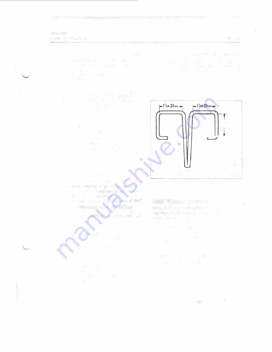
Fig.
21. The compression tool
COMPRESSION
TOOL
(Fig.
21)
The compression tool, necessary to compress the
output piston, is made from a 12 in. (30 cm.) length
of¼ in. (3 mm.) diameter iron wire.
Bend the wire back on itself in the centre to make
the middle "leg" of the tool. Follow with the six
other bends as shown in the illustration, finally
cutting the two ends so there is I¾ in. (45 mm.)
between them.
The centre "leg" is inserted into the output
cylinder bore and pressed down until the two
ends can be sprung apart and clipped under the
mounting flange of the cast body. The tool is
then pushed aside towards the control cylinder
bore to allow room to insert the circlip pliers.
Summary of Contents for ALPINE I SERIES: APLINE II SERIES
Page 1: ......
Page 189: ...Fis 21 Ball pin heirht checkinr fixture in position Details of items 1 to 4 In Fig 22...
Page 208: ...Fla 3 Exploded view of rear axle Hypoid Bevel Drive...
Page 220: ...Page 16 WSM 12 f Section G Rear Axle 0 QQ I I I I I t 0 ii 8 ts t 0 Cl 2 i J...
Page 247: ...Page6 WSM 124 Section J Steering N Iii it...
Page 299: ...Page 40 3 6 7 8 Fis 22 Se rvo unit exploded view Sect WSM 124 ion K Brakes 18 419 GZo 21...
Page 413: ..._ PRINTED IN ENGLAND 9Y WREN PRINTING CQ LTD LONDON...


