


114
Appendix
Appendix
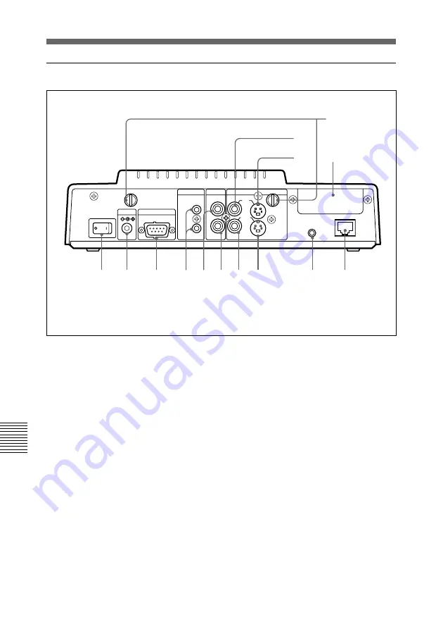
Location and Function of Parts and Controls
Main unit (rear)
1
POWER switch
Switch the Compact Processor to on.
2
DC 12V IN jack
Connect the supplied PCS-AC15 AC
adaptor to this jack.
3
T.120 connector (D-sub 9-pin,
male)
Connect an RS-232C device for data
input/output.
4
MIC1/MIC2 jacks/PLUG IN
POWER (phono jack)
Connect the optional PCS-A300
Microphone(s) to these jacks. These
provide the power supply to the
microphone(s) connected to these
jacks.
5
AUDIO IN jack (phono jack)
Connect to the audio output jack of
the external equipment.
6
AUDIO OUT jack (phono jack)
Connect to the audio input jack of the
TV monitor.
7
VIDEO AUX OUT jack (phono
jack)
Connect to the video input jack of the
external equipment.
8
VIDEO MONITOR OUT jack
(mini DIN 4-pin)
Connect to the video input jack of the
TV monitor.
POWER
DC12V
T.120
IN
AUX
2
AUX1
MONITOR
IR OUT
ISDN A
AUX
OUT
MIC
1
IN
OUT
2
(PLUG IN POWER)
AUDIO
VIDEO
1
2
3
4 5 6 7 8
9
0
qa
qs
qf
qd


