


7-29
FM 453 Servo Drive / Step Drive Positioning Module
C79000-G7076-C453-01
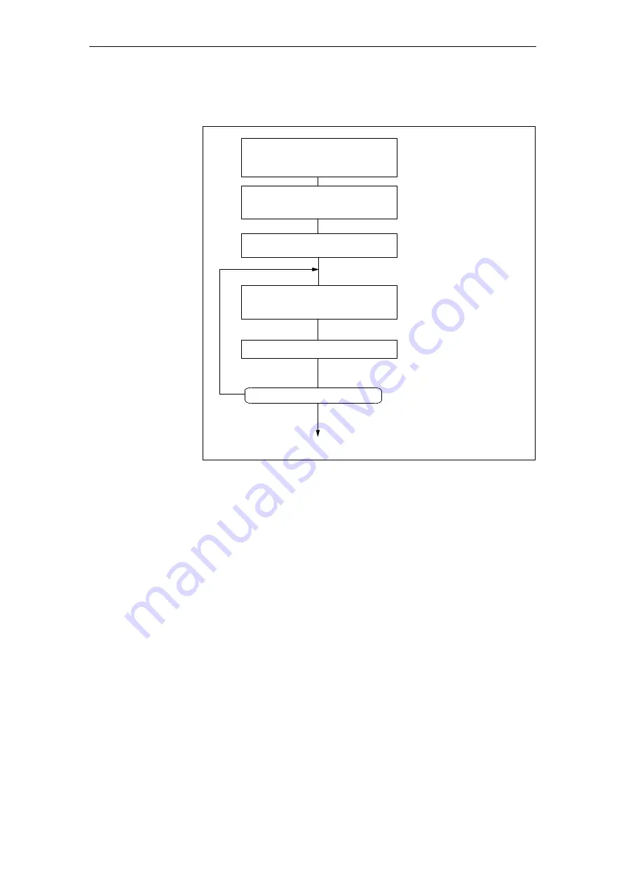
You can trigger test movements as follows as you perform optimization:
Select
Mode = jogging
Speed level 2
OVER = various values
Set
Speed level 1 = 0.1
@
v
max
Speed level 2 = 0.5
@
v
max
Set
Servo = ON
END
Yes
Start axis
Plus or minus direction
(be sure there is enough room!)
Evaluate axis response
Further testing desired?
No
Uniformity of movement - Over-
shoot - Positioning time
Fig. 7-15
Test Movements for Optimizing the Servo Control System
Servo drive
Set the following machine data in accordance with the drive time constant Ta
(Ta
real
) determined in Section 7.3.2 to the initial values for the optimization
steps below, e.g. for an axis in MSR 10
–3
mm:
S
Acceleration, delay
MD40 = MD41 [mm/s
2
] = 30
@
MD23 [mm/min] : Ta [ms]
S
Jolt time
MD42 (ms) = 0
S
Positioning loop amplification
MD38 (1/min) = 100,000 : Ta (ms)
The acceleration value that actually acts on the system is reduced by the time
response of the position control circuit - i.e. as a function of the K
v
value.
The maximum acceleration (a) in this setting can be attuned to the drive time
constant, and can be estimated as follows:
a
max
[mm/s
2
] = 16
@
MD23 [mm/min] : Ta
[ms]
To Trigger Test
Movements
Selecting Initial
Values of Re-
sponse-Defining
MD
Starting up the FM 453
Summary of Contents for SIMATIC FM 453
Page 6: ...vi FM 453 Servo Drive Step Drive Positioning Module C79000 G7076 C453 01 Preface ...
Page 14: ...xiv FM 453 Servo Drive Step Drive Positioning Module C79000 G7076 C453 01 Table of Contents ...
Page 378: ...Index 6 FM 453 Servo Drive Step Drive Positioning Module C79000 G7076 C453 01 Index ...


