Semiconductor Group
7-10
1997-10-01
Interrupt System
C541U
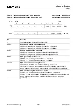
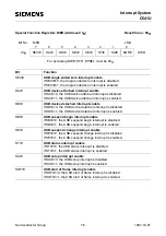
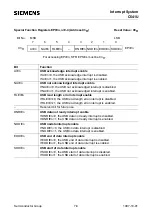
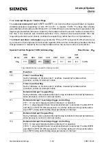
7.1.2 Interrupt Request / Control Flags
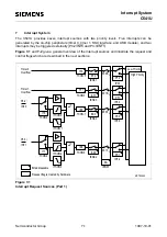
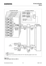
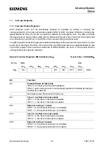
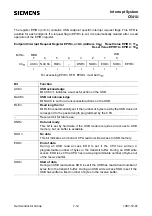
The external interrupts 0 and 1 (INT0 and INT1) can each be either level-activated or negative
transition-activated, depending on bits IT0 and IT1 in register TCON. The flags that actually
generate these interrupts are bits IE0 and lE1 in TCON. When an external interrupt is generated, the
flag that generated this interrupt is cleared by the hardware when the service routine is vectored too,
but only if the interrupt was transition-activated. lf the interrupt was level-activated, then the
requesting external source directly controls the request flag, rather than the on-chip hardware.
The timer 0 and timer 1 interrupts are generated by TF0 and TF1 in register TCON, which are set
by a rollover in their respective timer/counter registers. When a timer interrupt is generated, the flag
that generated it is cleared by the on-chip hardware when the service routine is vectored too.
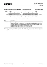
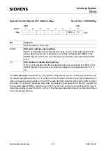
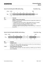
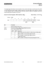
Special Function Register TCON (Address 88H)
Reset Value : 00H
The shaded bits are not used for interrupt control.
Bit
Function
TF1
Timer 1 overflow flag
Set by hardware on timer/counter 1 overflow. Cleared by hardware when
processor vectors to interrupt routine.
TF0
Timer 0 overflow flag
Set by hardware on timer/counter 0 overflow. Cleared by hardware when
processor vectors to interrupt routine.
IE1
External interrupt 1 request flag
Set by hardware when external interrupt 1 edge is detected. Cleared by hardware
when processor vectors to interrupt routine.
IT1
External interrupt 1 level/edge trigger control flag
If IT1 = 0, low level triggered external interrupt 1 is selected.
If IT1 = 1, edge triggered mode for external interrupt 1 is selected. The bits IE1TR
and IE1TF in SFR ITCON (see section 7.4) further define which signal transition
at pin INT1 (rising and/or falling edge) generates an interrupt.
IE0
External interrupt 0 request flag
Set by hardware when external interrupt 0 edge is detected. Cleared by hardware
when processor vectors to interrupt routine.
IT0
External interrupt 0 level/edge trigger control flag
If IT0 = 0, low level triggered external interrupt 0 is selected.
If IT0 = 1, edge triggered mode for external interrupt 0 is selected. The bits IE0TR
and IE0TF in SFR ITCON (see section 7.4) further define which signal transition
at pin INT0 (rising and/or falling edge) generates an interrupt.
TF1
TR1
TF0
TR0
88H
TCON
Bit No.
8FH
MSB
LSB
IE1
IT1
IE0
IT0
8EH
8DH
8CH
8BH
8AH
89H
88H
Summary of Contents for C541U
Page 1: ... 8 LW 026 0LFURFRQWUROOHU 8VHU V 0DQXDO http www siem ens d Sem iconductor ...
Page 7: ......
Page 21: ...Semiconductor Group 2 6 1997 10 01 Fundamental Structure C541U ...
Page 37: ...Semiconductor Group 4 6 1997 10 01 External Bus Interface C541U ...
Page 133: ...Semiconductor Group 6 88 1999 04 01 On Chip Peripheral Components C541U ...
Page 163: ...Semiconductor Group 8 8 1997 10 01 Fail Safe Mechanisms C541U ...
Page 185: ...Semiconductor Group 10 14 1997 10 01 OTP Memory Operation C541U ...

