


Semiconductor Group
6-46
1999-04-01
On-Chip Peripheral Components
C541U
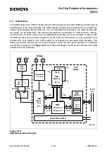
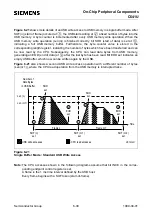
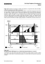
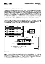
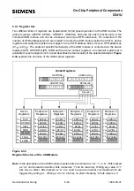
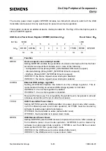
If bit SOFDE is set, buffer switching is done automatically after SOF (start of frame) has been
detected by the USB. Figure 6-29 describes this functionality for USB read access for this case.
The buffer which contains the latest data from the CPU is tagged valid for USB access (UBF=1) at
and the buffers are swapped if the USB buffer is empty. After the USB read access has occured
at
, this buffer assigned to USB is empty again (UBF=0) and can be swapped again as soon as
the CPU has filled its buffer (at
). The number of bytes in the buffer is less or equal MaxLen. The
MaxLen threshold is always active, but an occurrence of SOF (if SOFDE=1) or setting bit DONE by
software are used to tag the CPU buffer full before reaching MaxLen.
Figure 6-29
Dual Buffer Mode USB Read Access: Buffer Switching on SOF with SOFDE=1
1
2
3
Frame n
Frame n+1
Time
SOF (n)
set
Number of
Data Bytes
MaxLen
USB read accesses
CPU write accesses
MCT03409
Len1
SOF (n+2)
set
Time
SOF (n+1)
set
2
1
3
Page 0
Page 1
Page 1
Page 0
UBF = 0
Swap
Buffer
Swap
Buffer
UBF
= 0
USB Buffer
CPU Buffer
CBF
= 0
Len2
Len1
MaxLen
Len2
Summary of Contents for C541U
Page 1: ... 8 LW 026 0LFURFRQWUROOHU 8VHU V 0DQXDO http www siem ens d Sem iconductor ...
Page 7: ......
Page 21: ...Semiconductor Group 2 6 1997 10 01 Fundamental Structure C541U ...
Page 37: ...Semiconductor Group 4 6 1997 10 01 External Bus Interface C541U ...
Page 133: ...Semiconductor Group 6 88 1999 04 01 On Chip Peripheral Components C541U ...
Page 163: ...Semiconductor Group 8 8 1997 10 01 Fail Safe Mechanisms C541U ...
Page 185: ...Semiconductor Group 10 14 1997 10 01 OTP Memory Operation C541U ...