


Semiconductor Group
9-1
1997-10-01
Power Saving Modes
C541U
9
Power Saving Modes
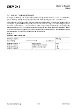
The C541U provides two power saving modes :
– Idle mode
– Power down mode.
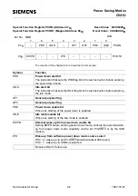
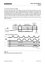
The functions of the power saving modes are controlled by bits which are located in the special
function registers PCON und PCON1. PCON is located at address 87H. PCON1 is located in the
mapped SFR area and is accessed with RMAP=1. Bit RMAP is located in SFR SYSCON (B1H)
bit 4.
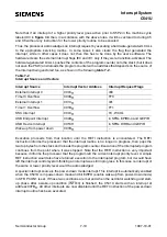
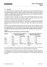
The bits PDE, PDS and IDLE, IDLS located in SFR PCON select the power down mode or the idle
mode, respectively. If the power down mode and the idle mode are set at the same time, power-
down takes precedence.
Furthermore, register PCON contains two general purpose flags. For example, the flag bits GF0 and
GF1 can be used to give an indication if an interrupt occurred during normal operation or during an
idle. Then an instruction that activates idle can also set one or both flag bits. When idle is terminated
by an interrupt, the interrupt service routine can examine the flag bits.
Summary of Contents for C541U
Page 1: ... 8 LW 026 0LFURFRQWUROOHU 8VHU V 0DQXDO http www siem ens d Sem iconductor ...
Page 7: ......
Page 21: ...Semiconductor Group 2 6 1997 10 01 Fundamental Structure C541U ...
Page 37: ...Semiconductor Group 4 6 1997 10 01 External Bus Interface C541U ...
Page 133: ...Semiconductor Group 6 88 1999 04 01 On Chip Peripheral Components C541U ...
Page 163: ...Semiconductor Group 8 8 1997 10 01 Fail Safe Mechanisms C541U ...
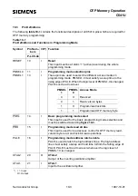
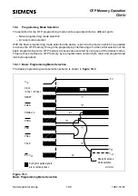
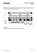
Page 185: ...Semiconductor Group 10 14 1997 10 01 OTP Memory Operation C541U ...