www.weg.net
Manual of Electric Motors
84
E
N
G
LI
S
H
The sleeve bearings used by WEG were not designed to support axial load continuously.
Under no circumstance must the motor be operated continuously at its axial clearance limits.
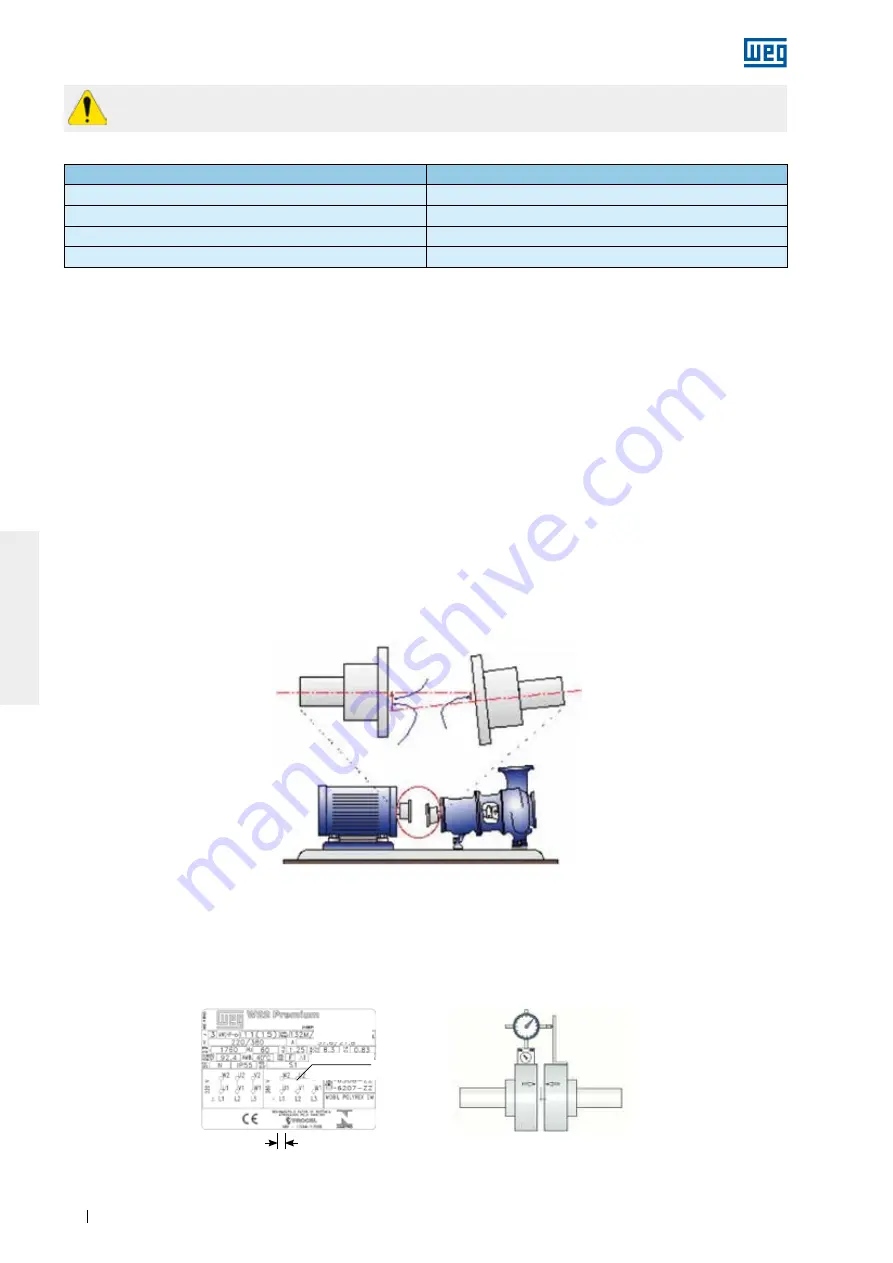
Figure 6.10
- Typical misalignment condition
* For Motors in accordance with API 541, the total axial clearance is 12.7 mm
For coupling evaluation consider the maximum axial bearing clearance as shown in Table 6.1.
The axial clearance of the driven machine and coupling influence the maximum bearing clearance.
Table 6.1
- Clearance used for sleeve bearings
Bearing size
Total axial clearance (mm)
9*
3 + 3 = 6
11*
4 + 4 = 8
14*
5 + 5 =10
18
7,5 + 7,5 = 15
6.5. LEVELING
The motor must be leveled to correct any deviations in flatness arising from the manufacturing process and the
material structure rearrangement. The leveling can be carried out by a leveling screw fixed on the motor foot or
on the flange or by means of thin compensation shims. After the leveling process, the leveling height between
the motor mounting base and the motor cannot exceed 0.1 mm.
If a metallic base is used to level the height of the motor shaft end and the shaft end of the driven machine, level
only the metallic base relating to the concrete base.
Record the maximum leveling deviations in the installation report.
6.6. ALIGNMENT
The correct alignment between the motor and the driven machine is one of the most important variables that
extends the useful service life of the motor. Incorrect coupling alignment generates high loads and vibrations
reducing the useful life of the bearings and even resulting in shaft breakages. Figure 6.10 illustrates the
misalignment between the motor and the driven machine.
Alignment procedures must be carried out using suitable tools and devices, such as dial gauge, laser alignment
instruments, etc.. The motor shaft must be aligned axially and radially with the driven machine shaft.
The maximum allowed eccentricity for a complete shaft turn should not exceed 0.03 mm, when alignment is
made with dial gauges, as shown in Figure 6.11. Ensure a gap between couplings to compensate the thermal
expansion between the shafts as specified by the coupling manufacturer.
Motor shaft
Driven machine shaft
Max.
misalignment
Driven machine
offset (mm)
Motor
offset (mm)
Figure 6.11
- Alignment with dial gauge
Parallel alignment
Angular alignment
GAP
Dial gauge
Line
Reference
Dial gauge
Page 155
Summary of Contents for BN 5-12 Series
Page 13: ...TAB 1 DEVICE DATA SHEETS ...
Page 18: ...TAB 2 APPROVED SUBMITTAL ...
Page 23: ...All data subject to change without notice 1 800 ASK 4WEG www weg net 14 ...
Page 26: ...Your advantages our pumps ...
Page 45: ...ADV 2 13E And what can we get flowing for you Your nearest contact Or visit www seepex com ...
Page 117: ...TAB 3 INSTALLATION OPERATIONS AND MAINTENANCE ...
Page 133: ...Page 37 ...
Page 233: ...www weg net Manual of Electric Motors 64 ENGLISH Figure 2 1 IEC motor nameplate Page 135 ...
Page 234: ...www weg net Manual of Electric Motors 65 ENGLISH Figure 2 2 NEMA motor nameplate Page 136 ...
Page 306: ...TAB 4 AS BUILTS AND SUPPLEMENTAL INFORMATION ...
Page 307: ...R Page 29 ...
Page 308: ...R Page 30 ...


