Date Code 20011205
Inputs, Outputs, Timers, and Other Control Logic
7-41
SEL-311A Instruction Manual
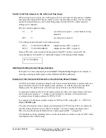
Switch to Setting Group 4 as the Active Setting Group
When setting Group 4 is the active setting group, the circuit breaker closing is always disabled
and optoisolated input IN102 has no control over the circuit breaker closing. The text settings
cannot be changed (they are used in all setting groups), but the SEL
OGIC
control equation
settings can be changed:
SEL
OGIC
control equation settings:
CL
= 0
(set directly to logical 1—circuit breaker closing
disabled)
DP1
= 0
(set directly to logical 0)
Text settings (remain the same for all setting groups):
DP1_1 = 52 CLOSE ENABLED
(displayed when DP1 = logical 1)
DP1_0 = 52 CLS DISABLED
(displayed when DP1 = logical 0)
Because SEL
OGIC
control equation display point setting DP1 is always at logical 0, the
corresponding text setting DP1_0 continually displays in the rotating default displays:
52 CLS DISABLED
Additional Rotating Default Display Example
See Figure 5.4 and accompanying text in
Section 5: Trip and Target Logic
for an example of
resetting a rotating default display with the TARGET RESET pushbutton.
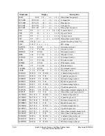
Displaying Time-Overcurrent Elements on the Rotating Default Display
The LCD can display the pickup settings for the time-overcurrent elements in primary units via a
special character sequence in the display points equations. As with the previously described
display points, the operator does not need to press any buttons to see this information.
To program a display point to show the pickup setting of a time-overcurrent element, first enter
the two-character sequence “::” (double colon) followed by the name of the desired time-
overcurrent element pickup settings for 51PP or 51GP.
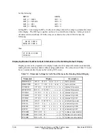
For example with the factory default settings for 51PP and CTR, setting DP1_0 = ::51PP will
display
1200.00 A pri
.
The relay calculates the value to display by multiplying the 51PP setting (6.00 A secondary) by
the CTR setting (200), arriving at 1200.00 A primary. The relay displays the display point
DP1_0 because the factory default SEL
OGIC
control equation DP1 = 0 (logical 0).
The calculations for the remaining time-overcurrent elements are similar, except for 51GP which
is multiplied by the CTRP setting.
Summary of Contents for SEL-311A
Page 6: ......
Page 8: ......
Page 10: ......
Page 24: ......
Page 40: ......
Page 66: ......
Page 96: ......
Page 98: ......
Page 112: ......
Page 114: ......
Page 122: ......
Page 170: ......
Page 202: ......
Page 204: ......
Page 246: ......
Page 248: ......
Page 286: ......
Page 290: ......
Page 304: ......
Page 306: ......
Page 334: ......
Page 384: ......
Page 386: ......
Page 394: ......
Page 398: ......
Page 402: ......
Page 404: ......
Page 410: ......
Page 412: ......
Page 426: ......
Page 444: ......
Page 460: ......
Page 474: ......


