Date Code 20011205
Setting the Relay
9-21
SEL----311A Instruction Manual
Line Settings
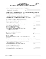
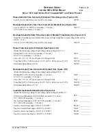
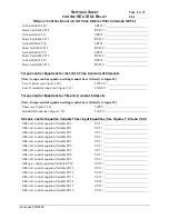
Refer to Settings Sheet 1.
Line impedance settings Z1MAG, Z1ANG, Z0MAG, and Z0ANG are used in distance relaying,
fault locator (see
Fault Location
in
Section 12: Standard Event Reports and SER
) and in
automatically making directional element settings Z2F and Z0F (see
Settings Made
Automatically
in
Section 4: Loss-of-Potential Logic, CCVT Transient Detection,
Load-Encroachment, and Directional Element Logic
). A corresponding line length setting (LL)
is also used in the fault locator.
The line impedance settings Z1MAG, Z1ANG, Z0MAG, and Z0ANG are set in
W
secondary. To
convert line impedance (
W
primary) to
W
secondary:
W
primary • (CTR/PTR) =
W
secondary
where:
CTR = phase (IA, IB, IC) current transformer ratio
PTR = phase (VA, VB, VC) potential transformer ratio (wye-connected)
Line length setting LL is unitless and corresponds to the line impedance settings. For example, if
a particular line length is 15 miles, enter the line impedance values (
W
secondary) and then enter
the corresponding line length:
LL
=
15.00
(miles)
If the same length of line is measured in kilometers rather than miles, then enter:
LL
=
24.14
(kilometers)
Enable Settings
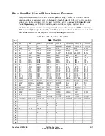
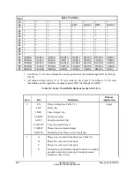
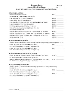
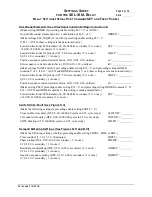
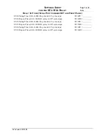
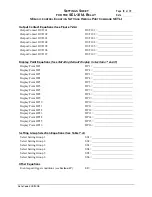
Refer to Settings Sheets 1, 2, and 13.
The enable settings on Settings Sheets 1 and 2 (E21P through EADVS) control the settings that
follow, through Sheet 7. Enable setting, EBMON, on Settings Sheet 13 controls the settings that
immediately follow it. This helps limit the number of settings that need to be made.
Each setting subgroup on Settings Sheets 2 through 7 has a reference back to the controlling
enable setting. For example, the residual time-overcurrent element settings on Sheet 4 (settings
51GP through 51GRS) are controlled by enable setting E51G.
Other System Parameters
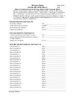
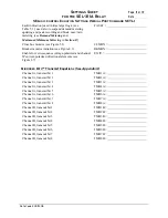
Refer to Settings Sheet 12.
The global settings NFREQ and PHROT allow you to configure the SEL
-
311A Relay to your
specific system.
Set NFREQ equal to your nominal power system frequency, either 50 Hz or 60 Hz.
Set PHROT equal to your power system phase rotation, either ABC or ACB.
Summary of Contents for SEL-311A
Page 6: ......
Page 8: ......
Page 10: ......
Page 24: ......
Page 40: ......
Page 66: ......
Page 96: ......
Page 98: ......
Page 112: ......
Page 114: ......
Page 122: ......
Page 170: ......
Page 202: ......
Page 204: ......
Page 246: ......
Page 248: ......
Page 286: ......
Page 290: ......
Page 304: ......
Page 306: ......
Page 334: ......
Page 384: ......
Page 386: ......
Page 394: ......
Page 398: ......
Page 402: ......
Page 404: ......
Page 410: ......
Page 412: ......
Page 426: ......
Page 444: ......
Page 460: ......
Page 474: ......

