14-4
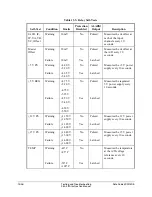
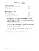
Application Settings for SEL-2PG10 Relays
Date Code 20011205
SEL-311A Instruction Manual
SEL-311A
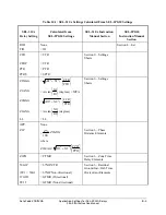
Relay Setting
Calculated from
SEL-2PG10 Settings
SEL-311A Instruction
Manual Section
SEL-2PG10
Instruction Manual
Section
51GP
= 67NP/CTR
Section 3—Residual
Ground Time-
Overcurrent Element
51GC
U1*
U2
U3
U4
= 67NC
= 1
= 2
= 3
= 4
51GTD =
67NTD
51GTC
= 67NC (51GTC is an SEL-311A
SEL
OGIC
setting)
(= 1
= Non-Directional)
(= 32GF
= Torque Controlled)
ORDER
Q
V
I
= 32QE
= 32VE
= 32IE
Section 4—Directional
Control for Ground
Distance and Residual
Ground Overcurrent
Elements
* Curve U1 in the SEL-311A is slightly different from curve 1 in the SEL-2PG10. Time dial
adjustments may be necessary.
Note
: SEL-311A phase-to-phase fault detector setting (50PP1) is set to its minimum value and
hidden. This corresponds to SEL-2PG10 setting 50L.
Summary of Contents for SEL-311A
Page 6: ......
Page 8: ......
Page 10: ......
Page 24: ......
Page 40: ......
Page 66: ......
Page 96: ......
Page 98: ......
Page 112: ......
Page 114: ......
Page 122: ......
Page 170: ......
Page 202: ......
Page 204: ......
Page 246: ......
Page 248: ......
Page 286: ......
Page 290: ......
Page 304: ......
Page 306: ......
Page 334: ......
Page 384: ......
Page 386: ......
Page 394: ......
Page 398: ......
Page 402: ......
Page 404: ......
Page 410: ......
Page 412: ......
Page 426: ......
Page 444: ......
Page 460: ......
Page 474: ......

