SAFEDOCK®
Safegate Group
Manual
Date: 6 February 2015
Chapter: 4A Stand Configuration Utility
Version: 2.7
Page 12 of 26
how the mirrors are mounted on the axis of the mirror motor. Negative values
are to the left/up, positive to the right/down, from the system point of view.
3.
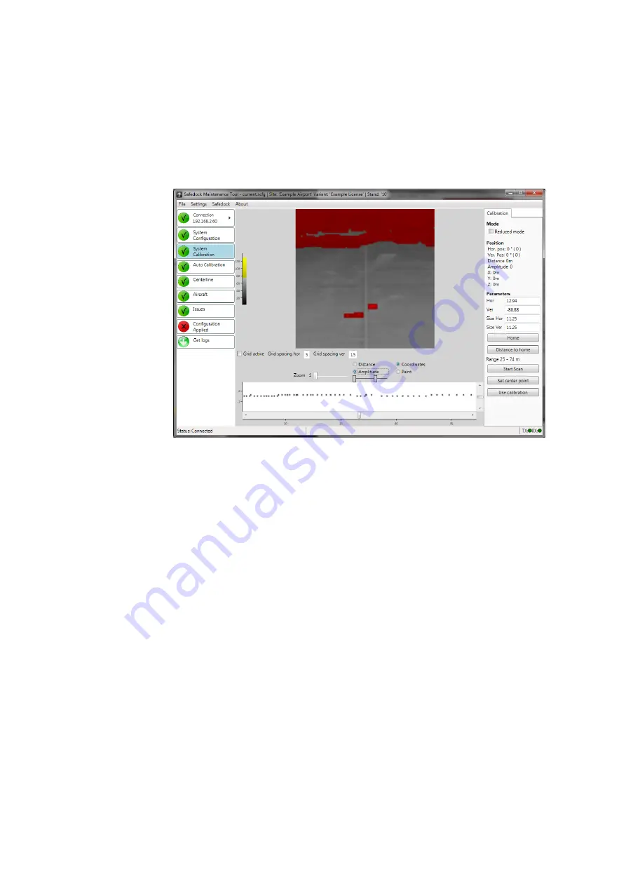
Press the “Start Scan” button and wait for the application to build an image of
the defined area. While the image is being built, a counter will indicate how
many scans there are left until completion.
4. You can choose to show the scanned image in a multi-colour scale (when
“Distance” is selected) and the in a blue-white gradient scale (when
“Amplitude” is selected), see figures below.
FIGURE 4A.6 - SYSTEM CALIBRATION FEATURE
– COLOUR SCREEN
5.
Next, use the paint tool (“Paint” button) to mask/hide those areas in the image
that should not be considered as the ground. Use left-click to mask and right-
click to erase the mask.
6. When all non-
ground areas have been masked, press the button “Use
Calibra
tion”. A dialog will be displayed, asking for confirmation.
7. Verify that the point-graph (with a white background) in the lower part of the
window accurately represents the silhouette of the area in the middle of the
newly masked image. In most cases, the points should form a straight line.
4.4.2
Alternate Calibration Procedure
If conditions are such that they prevent the system from obtaining a good image of the
apron, an alternate method for calibration can be used. The procedure is as follows:
1.
Check the “Reduced mode” checkbox on the right side (this disables the
Paint-option).
2. Press and hold
Ctrl
and left-click along the centreline (use reflexes while
scanning the image if it is not visible). For each click, a new marker will be
placed. Two markers are sufficient in most cases but if there are slopes or
rises in the apron you should place one marker on each top/bottom.
a. When the first marker is placed, a second marker in a different colour is
placed to the right. This marker shall be moved to the side as far away as
possible from the centre of the image, while still being placed on an area
where there is ground and within the inner and outermost marker. Again,
use reflexes if needed.
Summary of Contents for safedock
Page 1: ...SAFEDOCK Manual...
Page 2: ...Note This page is blank for convenient double sided printing...
Page 225: ......
Page 227: ......
Page 228: ......
Page 232: ......
Page 235: ......
Page 236: ......
Page 237: ......
Page 240: ......
Page 241: ......
Page 242: ......
Page 244: ......
Page 245: ......
Page 250: ......
Page 251: ......
Page 252: ......
Page 253: ......
Page 254: ......
Page 255: ......
Page 256: ......
Page 257: ......
Page 259: ......
Page 260: ......
Page 261: ......
Page 263: ......
Page 264: ......
Page 266: ......
Page 267: ......
Page 268: ......
Page 271: ...CANCEL ENTER...
Page 272: ......
Page 273: ...K73 K74...
Page 274: ......
Page 276: ......
Page 277: ......
Page 278: ......
Page 279: ...K73...
Page 280: ......
Page 282: ......
Page 283: ......
Page 284: ......
Page 287: ......
Page 288: ......
Page 289: ......
Page 290: ......
Page 293: ......
Page 294: ......
Page 295: ......
Page 298: ......
Page 299: ......
Page 300: ......
Page 302: ......
Page 304: ......
Page 310: ......
Page 311: ......
Page 312: ......
Page 313: ......
Page 314: ......
Page 315: ......
Page 316: ......
Page 317: ......
Page 318: ......
Page 319: ......
Page 320: ......
Page 321: ......
Page 322: ......
Page 323: ......
Page 324: ......
Page 325: ......
Page 326: ......
Page 327: ......
Page 328: ......
Page 329: ......
Page 335: ......
Page 336: ......
Page 337: ......
Page 340: ......
Page 346: ......
Page 347: ......


