2)
After you connect the copper module to the Ethernet network through the connector, the Link/ACT status is on.
Otherwise, please check the connector.
Precaution
If the SFP+ copper module cannot be inserted to the end, do not push it forcefully. Please try the other end of the
module.
Do not touch the connecting finger on the module.
Do not squeeze, bend or fold the copper cable, which may cause system performance degradation or data loss.
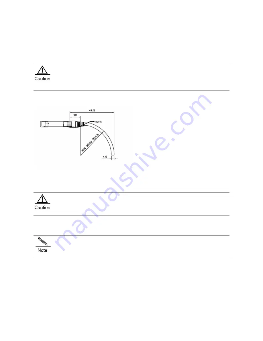
After the cable is plugged, make sure that the bending radius is greater than 5 times of the cable diameter.
Too small bending radius may cause damage to the copper cable. For example. If the cable diameter is
4.9mm, the bending radius should be 24.5mm at least, as shown in figure 3-38:
Figure 3-38 Bending Radius and Cable Diameter
Use an SFP+ cable to connect two SFP+ ports close to each other. Take the following steps to install the SFP+ module:
1)
Wear an anti-static wrist strap close to your skin and have it properly grounded.
2)
Take out the SFP+ module you want to install from the packing bag.
3)
Plug the SFP+ cable to the SFP+ port through the connector. Pay attention to the proper end for connection.
During the operation, make sure that the cable’s bending radius is no less than eight times as much as its
diameter.
Installing 40-Gigabit QSFP+ Modules
To avoid damaging components due to operation errors, read this section carefully before installing
40-Gigabit QSFP+ modules.
Take the following steps to install 40-Gigabit QSFP+ modules:
1)
Turn up the handle of the module into the top bail-clasp latch. Hold both sides of the module and push the module
into place (You can feel that the module is placed in position with a click sound), as shown in figure 3-39
2)
Push the module gently into the QSFP+ module slot until you hear a click, indicating the module is correctly installed,
as shown in figure 3-40.
Figure 3-39 Installing the QSFP+ Module Equipped with a Bail-Clasp Latch
Summary of Contents for RG-S8605E
Page 1: ...RG S8600E Series Switches Hardware Installation and Reference Guide V1 09...
Page 63: ...Figure 2 2 Preventing EMI on RG S8607E Figure 2 3 Preventing EMI on RG S8610E...
Page 86: ...Figure 3 21 Grounding Point on the Rear of the RG S8610E Switch...
Page 116: ...Figure 7 12 Replacing the Module for RG S8610E...
Page 120: ...Note A Fan modules to be removed B Fan modules to be installed...
Page 132: ......


