Storage
Temperature
-40 to 70°C
Operating Humidity
10%-90% RH (non-condensing)
MTBF 290,000
hours
Weight
Net weight: 3.80 kg
Dimensions
(W x D x H)
399 mm x 440 mm x 40.18 mm
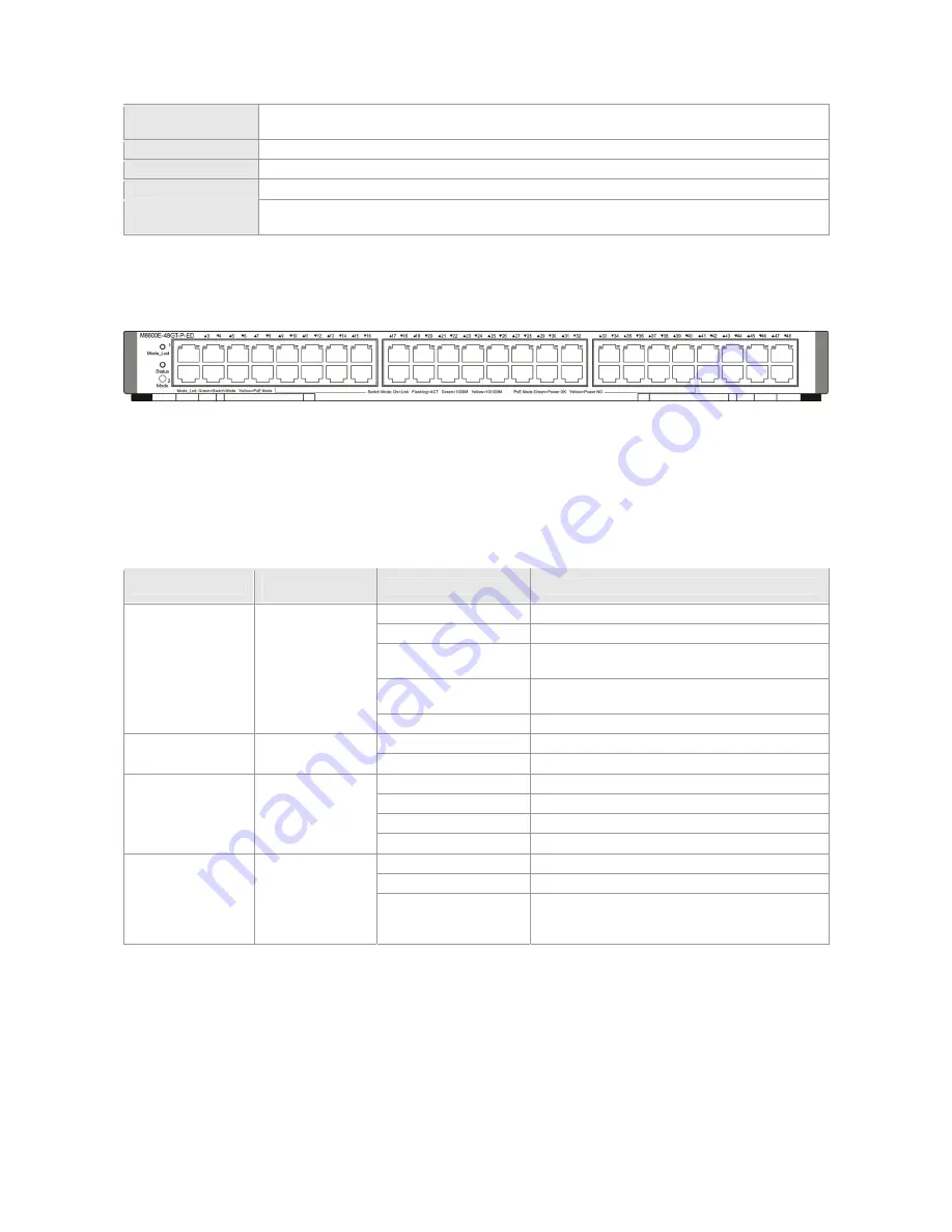
M8600E-48GT-P-ED
Module Appearance
Figure 0-20 Appearance of the M8600E-48GT-P-ED Module
External Port
The M8600E-48GT-P-ED provides 48 copper ports. The RJ45 ports support auto-negotiation at 10/100/1000 Mbps and
hot swapping. Copper ports do not support half-duplex at 10/100Mbps.
PoE Power Supply
The M8600E-48GT-P-ED supports IEEE802.3af and IEEE802.3at PoE. It adopts the Alternative A mode for transmitting
power over Ethernet cabling, that is power is transmitted through cable pairs 1, 2, 3 and 6.
LED
LED
Identification on
the panel
Status
Meaning
Off
The module is NOT receiving power.
Solid red
The module is faulty.
Solid yellow
High temperature alarm. The system keeps
operating but the performance is affected
Blinking green
Initialization is in progress. Continuous blinking
indicates errors.
System LED
Status
Solid green
The module is operational
Solid green
Switching mode
Mode LED
Mode_Led
Solid yellow
PoE mode
Off
The port link is NOT connected.
Solid green
The port is connected at 1000Mpbs.
Solid yellow
The port is connected at 10/100Mbps.
RJ45 port LED (in
switching mode)
Link/ACT
Blinking
The port is transmitting and receiving data.
Off
The port does NOT provide PoE power supply.
Solid green
The port provides PoE power supply
RJ45 port LED(in
PoE mode)
Link/ACT
Solid yellow
The port is overloaded and short-circuited,
Power overload causes failure to provide PoE
power supply.
Button
The Mode button has the following functions:
Press the “Mode” button to change the mode between switching and PoE. The green LED indicates switching mode
and the yellow LED indicates PoE mode.
In PoE mode, hold down the “Mode” button for three seconds to disable PoE power supply and switch to the
switching mode. The LED turns green to indicate switching mode. After power on, the system is powered by PoE
power supply by default.
Specifications
Summary of Contents for RG-S8605E
Page 1: ...RG S8600E Series Switches Hardware Installation and Reference Guide V1 09...
Page 63: ...Figure 2 2 Preventing EMI on RG S8607E Figure 2 3 Preventing EMI on RG S8610E...
Page 86: ...Figure 3 21 Grounding Point on the Rear of the RG S8610E Switch...
Page 116: ...Figure 7 12 Replacing the Module for RG S8610E...
Page 120: ...Note A Fan modules to be removed B Fan modules to be installed...
Page 132: ......


