INSTALLATION INSTRUCTIONS
SeaBat 8160
Operator‟s Manual
Page 21
October 6, 2011
Version 5
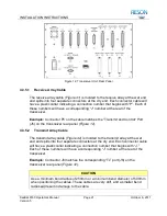
Figure 12: Transceiver Unit, Rear Panel
4.3.5.1
Receive Array Cable
The receive array cable (
) is molded to the receive array at the wet end
and splits into four separate connectors at the dry end. Each connector cable will
have a plastic collar indicating a connection number that begins with “P”. Each of
these numbers will have a corresponding
“J” number at the rear of the
transceiver.
Example:
Connect
or P5 on the cable matches the “Transmit and Control” Port
(J5) on the transceiver rear panel (
4.3.5.2
Transmit Array Cable
The transmit array cable (
) is molded to the transmit array at the wet
end and splits into four separate connectors at the dry end. Each connector cable
will have a plastic collar indicating a connection number that begins with “J.”
Each of these numbers will have a corresponding “J” number at the rear of the
transceiver.
Example:
Connector J6 matches the corresponding “Tx” port (J6) on the
transceiver rear panel (
CAUTION
Use a minimum bend radius of 250mm or a minimum bend diameter of 500mm
when positioning the cables. These cables are very stiff, and a smaller bend
radius will result in damage to the cable.


