INTERFACE SPECIFICATIONS
SeaBat 8160
Operator‟s Manual
Page 85
October 6, 2011
Version 5
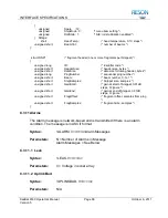
unsigned short
min_range;
//sonar filter settings
unsigned short
max_range;
unsigned short
min_depth;
unsigned short
max_depth;
unsigned char
filters_active;
//range/depth filters active
//bit 0
– range filter (0 = off, 1 = active)
//bit1
– depth filter (0 = off, 1 = active)
unsigned char
flags;
//bit 0
– Roll stabilization flag (0 = off, 1 = on)
unsigned char
spare[2];
//spare field for future growth
short
temperature;
//temperature at Sonar Array (deg C * 10)
short
beam_count;
//number of sets of beam data in packet
unsigned short
range[n];
//range for beam N = beam_count
//range units = sample cells * 4
unsigned char
quality[cnt];
//packed quality array (two 4 bit values/char)
//cnt = n/2 if beam count even, n/2 +1 if odd.
//cnt then rounded up to next even number
//e.g. if beam count = 101, cnt = 52
//unused trailing quality values set to zero
//bit 0
– brightness test (0 = failed, 1 = passed)
//bit1
– colinearity test (0 = failed, 1 = passed)
//bit2
– amplitude bottom detect used
//bit3
– phase bottom detect used
//bytes are populated high order nibble first
//with the higher 4 bits for the first sounding and
//the lower 4 bits for the second sounding
//bottom detect can be amplitude, phase or both
unsigned short
intensity[n];
//intensities at bottom detect * 8
unsigned short
checksum;
//checksum for data packet
};
C.3.9 Sidescan Imagery Packets
When the sidescan option is enabled, the sonar will output a left and right
sidescan packet for each sonar ping. The sidescan data will be generated using
the same ping as the bathymetry so it will be possible for the data collection
system or subsequent processing to use the bathymetry data to geographically
register the imagery. Since the sidescan data will be output by the sonar on
Ethernet, and this type of output has a limitation of 1,500 bytes or less, the ping
data from each beam may be broken up into multiple packets. The information
for the two beams will be output as a series of amplitude values, starting from the
outermost sample cell on the port side, through the center to the outermost
sample cell on the starboard side. The network transport protocol used is
UDP/IP.
The number of amplitude values output for each packet will vary with range. if
RMS or average modes are used, the data will be compressed to a maximum of
1024 samples per channel.


