background image

i

IMPORTANT NOTICES

General

How to discard this product

Discard this product according to local regulations for the disposal of industrial waste. For disposal 
in the USA, see the homepage of the Electronics Industries Alliance (http://www.eiae.org/) for the 
correct method of disposal.

How to discard a used battery

To see if your product has a battery, see the chapter on Maintenance. Follow the instructions be-
low if a battery is used. Tape the + and - terminals of battery before disposal to prevent fire, heat 
generation caused by short circuit.

In the European Union

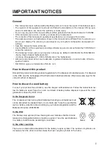
The crossed-out trash can symbol indicates that all types of batteries must 
not be discarded in standard trash, or at a trash site. Take the used batter-
ies to a battery collection site according to your national legislation and the 
Batteries Directive 2006/66/EU. 

In the USA

The Mobius loop symbol (three chasing arrows) indicates that Ni-Cd and 
lead-acid rechargeable batteries must be recycled. Take the used batteries 
to a battery collection site according to local laws.

In the other countries

There are no international standards for the battery recycle symbol. The number of symbols can 
increase when the other countries make their own recycle symbols in the future.

•  This manual has been authored with simplified grammar, to meet the needs of international users.
•  The operator of this equipment must read and follow the descriptions in this manual. Wrong oper-

ation or maintenance can cancel the warranty or cause injury.

•  Do not copy any part of this manual without written permission from Radio Holland or FURUNO.
•  If this manual is lost or worn, contact your dealer about replacement.
•  The contents of this manual and equipment specifications can change without notice.
•  The example screens (or illustrations) shown in this manual can be different from the screens you 

see on your display. The screens you see depend on your system configuration and equipment 
settings.

•  Save this manual for future reference.
•  Any modification of the equipment (including software) by persons not authorized by FURUNO will 

cancel the warranty.

•  The following concern acts as our importer in Europe, as defined in DECISION No 768/2008/EC.

- Name: Radio Holland Netherlands B.V.
- Address: Droogdokweg 71, 3089 JN Rotterdam, The Netherlands

•  All brand and product names are trademarks, registered trademarks or service marks of their re-

spective holders.

•  SD, SDHC Logos are trademarks of SD-3C, LLC.

Cd

Ni-Cd

Pb

Summary of Contents for RHRS-2014

Page 1: ...OPERATOR S MANUAL RIVER RADAR RHRS 2014 Model www radioholland nl...

Page 2: ...Elemental Chlorine Free The paper used in this manual is elemental chlorine free All rights reserved Pub No OME 36140 D2 MISU RHRS 2014 B JAN 2013 D2 JAN 10 2018 00017687513...

Page 3: ...cle symbol The number of symbols can increase when the other countries make their own recycle symbols in the future This manual has been authored with simplified grammar to meet the needs of internati...

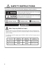
Page 4: ...tion Prohibitive Action Mandatory Action WARNING Radio Frequency Radiation Hazard The radar antenna sends the electromagnetic radio frequency RF energy This energy can be dangerous to you especially y...

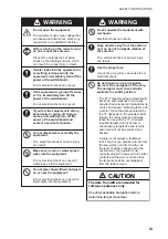
Page 5: ...n result if a liquid spills into the equipment Do not operate the equipment with wet hands Electrical shock can result Keep objects away from the antenna unit so as not to impede rotation of the anten...

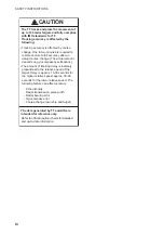
Page 6: ...pends on gyrocompass specifications Echo intensity Radar transmission pulse width Radar bearing error Gyrocompass error Course change own ship and target The amount of tracking delay is inversely prop...

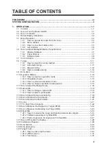
Page 7: ...1 13 1 10 3 How to select an orientation mode 1 15 1 10 4 How to change orientation mode presets 1 15 1 11 How to Select the Range Scale 1 16 1 12 Pulse width 1 18 1 12 1 How to change a pulse width 1...

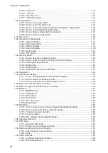
Page 8: ...29 6 Speed and movement indications 1 44 1 30 Interswitch 1 44 1 31 Dual Radar Display 1 45 1 31 1 How to Enable Disable the Dual Radar Display 1 46 1 31 2 How to select the reference radar 1 47 1 31...

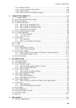
Page 9: ...ectors 2 10 2 10 2 Vector mode and length 2 11 2 11 Past Position Display 2 11 2 11 1 How to select the dot number and interval of the past position 2 11 2 11 2 Past position display mode 2 12 2 12 CP...

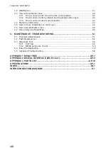
Page 10: ...w to Show Hide Marks on the Screen 4 4 4 6 How to Delete Marks Lines 4 4 4 7 How to Align the Radar Map 4 5 5 MAINTENANCE TROUBLESHOOTING 5 1 5 1 Preventive Maintenance 5 1 5 2 Parts Replacement 5 2 5...

Page 11: ...ch high resolution display in a single color or gradations of green or cyan according to echo strength Following are the main features Displays inland AIS targets Complies with ETSI EN 302 194 1 and E...

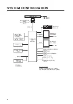
Page 12: ...102 26 rpm RSB 121A RTR 102 48 rpm PROCESSOR UNIT RPU 023 Sub Display NMEA1 HEADING SENSOR IEC61162 2 NMEA2 AIS IEC61162 2 NMEA3 NAV EQUIPMENT IEC61162 1 NMEA4 Doppler IEC61162 1 NMEA5 Alarm INS IEC6...

Page 13: ...e selection or the cursor Left click Right click RANGE Select display range Select the pulse width EBL Display Hide EBL Electronic bearing line VRM Display Hide VRM Variable range marker MENU Display...

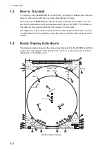
Page 14: ...symbols may not be shown depending on the display mode Radar display example 10 4m s Front 10 4m Aft 13 7m 4 8 kn 4 8 kn 4 8 kn SEA ROT RUDDER 8 2 km HEAD UP RD003016 STBY OFFCENT OFF HDG 123 4 MASTER...

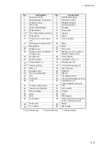
Page 15: ...ground color effective display area 26 Background color outside effective display area 27 Monitor brill 28 Panel dimmer 29 Docking mode 30 2 Acquisition zone 1 2 31 2 Target alarm 1 2 32 Heading line...

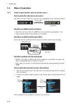
Page 16: ...value Press Move the cursor on the setting box respectively among GAIN STC and RAIN How to select the menu items on the menu window 1 Use the touch pad to select the menu item The selected menu item i...

Page 17: ...UTO CLOSING TIME menu 1 5 3 How to show the hidden icons If the radar can be set to hide some icons after a specified interval click the MENU icon to display the hidden icons Control unit Mouse Cursor...

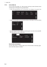
Page 18: ...Right click the ALARM icon at the top left corner then click 3 ALARM LIST HISTORY to show the Alarm list How to close a list window Click the close button u at the top right corner of the list window...

Page 19: ...an be adjusted as follows 1 Click the setting box for panel dimmer at the bottom left corner on the screen 2 Press the left button to decrease the dimmer the right button to increase the dim mer With...

Page 20: ...he BRL1 1 setting is fixed as a default setting You can edit the setting but when the system is turned off the default setting is restored To save a custom brilliance set select a setting other than B...

Page 21: ...1 7 Color Scheme You can select the color for echo and background color inside outside with the display icons Available colors You can set the customized color for the following items on COLOR DETAIL...

Page 22: ...rk green TRAIL COLOR GRN green WHT white GRN green C O L O R D E T A I L CHARACTER WHT white FIXED RING WHT white GYRO RING GRN green WHT white EBL VRM NAV LINE GRN green ALARM RED CURSOR GRN green Av...

Page 23: ...h between AUTO and MAN 1 8 2 Automatic tuning Click the tuning icon to select AUTO referring to paragraph 1 8 1 COLOR DETAIL CHARACTER GRN green RED WHT white FIXED RING GRN green WHT white GYRO RING...

Page 24: ...to start the ini tialization The tuning bar turns yellow and moves during the initialization Note 1 The display may appear incorrect during initialization caused by changes in pulse or tun ing levels...

Page 25: ...ing to the operation mode Orientation mode Range Units Screen size River mode circle only Sea mode circle and wide See section 1 9 1 10 2 Orientation mode Relative motion RM In relative motion own shi...

Page 26: ...ng signal If the compass fails the orientation mode changes to head up and the north marker dis appears COURSE UP The course up mode is an azimuth stabilized display in which a line connecting the cen...

Page 27: ...bility Heading L L RIVER mode SEA mode Head up RM Yes Yes Head up RM TB 9 No Yes Stern up RM Yes Yes North up RM 9 No Yes Course up RM 9 No Yes North up TM 9 9 No Yes Course up TM 9 9 No Yes HEAD UP H...

Page 28: ...n a target of interest comes closer reduce the range scale so that it appears in 50 90 of the display radius The available units for range are NM KM SM and KYD You can change the unit when installed L...

Page 29: ...In Sea mode the default unit is NM Range KM Range ring interval KM 0 125 0 025 0 25 0 05 0 5 0 1 0 8 0 2 1 2 0 2 1 6 0 4 2 0 4 4 1 8 2 16 4 32 8 64 16 Range NM Range ring interval NM 0 125 0 025 0 25...

Page 30: ...ick to lengthen the pulse width Appropriate pulse widths are preset to individual range scales If you are not satisfied with the current pulse width settings you may change them referring to paragraph...

Page 31: ...50 to 50 For manual mode 0 to 100 INSTALL 1 FTC 1 IR 1 TRAIL CUSTOM1 1 CUSTOM1 1 Right click CUSTOM MENU 1 BACK 2 EDIT 3 PRESET 1 BACK 2 USER NAME USER NAME 1 3 USER COMMENT CUSTOM4 4 4 GAIN STC RAIN...

Page 32: ...ntrol until the clutter has disappeared to leeward but a small amount of the clutter is visible windward For auto mode the setting range is 50 to 50 For manual mode 0 to 100 STC PRESET You can tune ST...

Page 33: ...e the setting range is 50 to 50 For manual mode 0 to 100 1 16 Cursor Within the radar display the cursor is shown by a plus sign When the cursor is outside the radar display it comes to an arrow Curso...

Page 34: ...e range to a target by two methods fixed range rings and the VRM Variable Range Marker How to measure the range with the fixed range rings Use the fixed range rings to get a rough estimate of the rang...

Page 35: ...EBL2 How to measure the bearing with an EBL 1 Click the EBL icon to display the EBL If the EBL already appears go to step 2 2 Click the EBL icon EBL1 or EBL2 The icon turns yellow 3 Put the cursor on...

Page 36: ...ove the origin of the EBL to measure the range and bearing between two targets 1 Click the EBL1 icon to activate EBL1 If the EBL already appears go to step 2 2 Right click anywhere in the radar displa...

Page 37: ...rget B The VRM adjusts to put the VRM ring on the target B The point selected at step 4 is the center of VRM 11 Read the bearing at the EBL icon and the range at the VRM icon EBL origin Target A Targe...

Page 38: ...o offset an EBL on page 1 24 2 Right click to quit the offset EBL 3 After waiting for a few minutes click the appropriate EBL icon to operate the EBL The icon turns yellow EBL origin EBL origin Target...

Page 39: ...able in SEA mode only However the setting is applied in RIVER mode also 1 In the SEA mode open MAIN MENU click MARK to show the MARK menu 2 Click EBL OFFSET BASE 3 Click the origin point of the offset...

Page 40: ...creen 2 Click to switch the off centering rate 20 40 60 or OFF How to off center the display 1 Click inside the effective display area to open CURSOR MENU 2 Click OFF CENTER 3 Click the off center poi...

Page 41: ...ce rejection Note When there is no interference turn off the interference rejecter so that you do not miss small targets 1 23 Echo Stretch The echo stretch feature enlarges the targets in the range an...

Page 42: ...a clutter on the screen so as not to erase weak targets Then do as follows Click the EAV echo average icon to switch the setting among EAV OFF EAV 1 EAV 2 EAV 3 1 25 Target Trails The trails of the ra...

Page 43: ...ments relative to your ship The stationary targets also show the trails To select the trail mode select the trail mode icon to switch the mode T G T S True mode or REL Relative mode For the ship speed...

Page 44: ...e icon The setting of trail time is different according to the operation mode RIVER mode 1 25 sec 2 5 sec 5 sec When the antenna rotation speed is 26 rpm the 1 25 sec is the same picture as the 2 5 se...

Page 45: ...the SEA mode serves to alert the navigator to targets ships landmasses etc com ing in out a specific area with audio vi sual alarms 1 26 1 How to set a target alarm The procedure below shows how to s...

Page 46: ...ting the alarm zone 1 Open MAIN MENU click ALARM to show the ALARM window 2 Click TARGET ALARM 3 Click ALR1 MODE or ALR2 MODE 4 Click the alarm type IN or OUT 5 Click outside the menu window to close...

Page 47: ...audio alarm but does not stop flashing of the offending target 1 26 5 How to sleep a target alarm temporarily You can sleep a target alarm zone when its use is not immediately needed The alarm zone re...

Page 48: ...port NAV LINE for starboard VRM MENU BRL2 3 ECHO B IN OUT MONI PANL AZ1 AZ2 ALR1 ALR2 HL OFF TT ON LIST EBL1 123 4 EBL2 82 9 T T NM GRN BLK D GRN 50 15 INSTALL 1 AIS FLT VRM1 1 567 VRM2 0 160 NAV 0 16...

Page 49: ...ror Messages 1 28 1 Alarm indication When the alarm is generated the ALARM icon flashes in red and the audio alarm sounds How to acknowledge the alarm Click the ALARM ACK icon to acknowledge the alarm...

Page 50: ...ated TUNE CONTROL Radar tuning problem FAN MOTOR Fan motor has stopped SENSOR ERROR NO GYRO Loss of gyrocompass heading signal NO LOG Loss of log speed signal NO EPFS No position data NO ECHO SOUNDER...

Page 51: ...in the list in red text latest to ear liest Alarm indication Meaning Alarm indication Meaning TRIG No trigger GYRO No gyro VIDEO No video LOG No log AZ No azimuth EPFS No EPFS HL No heading ROT No RO...

Page 52: ...ROT signal fed from an ROT sensor If the ROT data is lost the indication ROT ALARM appears in ALARM LIST and the audio alarm sounds To acknowledge loss of the ROT signal click the ALARM ACK icon 1 29...

Page 53: ...information with the DOCK icon as shown below 1 29 3 Wind speed and direction Wind speed and direction are provided with the dock ing information display Relative speed is indicated dig itally and di...

Page 54: ...The stern mode shows aft depth on top Depth display format Depth can be shown digitally or in graph form 1 Open MAIN MENU click NAV DATA 2 Click DEPTH 3 Click GRAPH TYPE 4 Click a required option NUM...

Page 55: ...RADIO ZEELAND 4 10 40 OTHERS 10 20 50 100 200 500 7 Click BACK to go back the DEPTH window 8 Click TIME SCALE 9 Click the time scale horizontal axis for the depth graph among 15 sec 30 sec 1 min and...

Page 56: ...ignal transfers the video and control signals You can connect three inter switches Set radar display and antenna groups from the ANTENNA icon When you switch to a different antenna the heading skew an...

Page 57: ...main radar are applied to the picture from the external radar Operation mode RIVER SEA Range and range unit The image from two or more radars may be shown together on one ra dar display This allows y...

Page 58: ...play a part of the external radar image in the window on the main radar 4 Click outside the menu window to close the menu Note 1 The dual radar function becomes inoperative when the external radar is...

Page 59: ...r The area outside that set here is where the image from the external radar will be displayed EXT Set external radar s antenna as reference point and set display area of ex ternal radar The area outsi...

Page 60: ...ata Some settings for own ship vector are required as fol lows Menu items Settings Reference OWN SHIP VECTOR COURSE paragraph 1 39 4 VECTOR TIME Set a time between 30 seconds to 6 min utes Note The sh...

Page 61: ...category are shown on the below and on the next page Some items have multilevel options Programs available in the ECHO menu Programs available in the STD KEY menu Programs available in the TT AIS menu...

Page 62: ...N MAP ALIGN MARK LINE ALL DELETE BARGE ALL DELETE F1 OPERATION RIVER mode only SEA mode only 1 BACK 2 USER NAME 1 BRL1 1 BRL1 2 BRL1 3 BRL1 4 3 USER NAME 2 BRL2 1 BRL2 2 BRL2 3 BRL2 4 4 USER NAME 3 BR...

Page 63: ...ation depending on the ship orientation in north up and true motion modes How to hide the heading line temporarily To temporarily hide the heading line to look at targets existing dead ahead of own sh...

Page 64: ...the bear ing scale in accordance with the compass signal in the head up head up TB or stern up mode Note It is not possible to de lete the north mark The north mark is always indicated while a headin...

Page 65: ...Click the barge display icon to show or hide Own ship Barge mark Barge mark at the bottom left corner on the screen MENU ON 2 WHT ON CYA DOCK OFF BRL2 3 ECHO B IN GRN BLK MARK MARK BARGE BARGE Barge...

Page 66: ...axis are displayed and the barge mark is drawn with a dashed line 5 Click the 2nd point to complete the barge mark The mark changes to the rectan gle with the solid line MENU BARGE ON WHT ON CYA DOCK...

Page 67: ...mark directly by putting the cursor on the line of the barge mark In this case go to step 3 2 Set ON at the display icon to display the barge mark to edit The selected barge mark turns red 3 Right cli...

Page 68: ...o show SPEED MENU Speed Depth Own ship position Time to the cursor position Wind Date ROT graph Rudder graph AUTOPILOT graph 1 BACK 2 COLOR GRN BLU YEL CYA MAG WHT 3 BARGE ALL DELETE NO YES BARGE DELE...

Page 69: ...SET CURRENT SPD Set the speed of the tide NAV AID Click the source of ship position data GPS or DEAD RECKON dead reckoning MANUAL L L For DEAD RECKON enter the latitude and longitude using the soft w...

Page 70: ...not shown LOCAL TIME ADJ If LOCAL is selected at DATE TIME set the time difference between local time and UTC time 1 35 3 Time to the cursor position The time from own ship to the cursor posi tion TT...

Page 71: ...h The rudder graph shows the rudder angle There is no NMEA signal and also no indi cation To set the rudder graph scale 1 Open MAIN MENU then click NAV DATA 2 Click RUDDER SCALE 3 Click the desired sc...

Page 72: ...mode the autopilot controls the ROT so that actual heading becomes same as com manded one 3 Neither FU nor AP mode When the autopilot is in neither FU nor AP mode the autopilot graph shows ROT command...

Page 73: ...right corner on the screen to show the CUSTOM MENU window 2 Click EDIT Customized menu settings 4 sets USER 1 USER 2 USER 3 USER 4 16 sets Click INSTALL 1 FTC 1 IR 1 ES 2 EAV 3 TRAIL 2 50sec 00m03s R...

Page 74: ...n to finish 7 Click the menu to set in the EDIT menu 8 Click the setting for each menu 9 Click SAVE QUIT to save the setting EDIT 1 BACK 2 USER NAME USER NAME 1 3 USER COMMENT CUSTOM4 4 4 GAIN STC RAI...

Page 75: ...that is compatible with the specifications of the SD card The SD Memory Card Formatting Software made by Panasonic is an example How to set an SD card The processor unit has two slots for SD cards The...

Page 76: ...the remaining capacity of the SD card selected at DRIVE SELECT SAVE DATA Save the file stored on the following file group set at NAME Set the name with the software keyboard Click the END key to comp...

Page 77: ...8 2 Icons You can show or hide some labels and auto hide them after the specified period elapsed How to select the menu icons to display 1 Open MAIN MENU click DISPLAY 2 Click HIDDEN ICON 3 Click each...

Page 78: ...2 Menu transparency You can make the menu window transparent or opaque as follows Note Alpha blending technology is used for transparency effects 1 Open MAIN MENU click DISPLAY 2 Click TRANPARENCY 3 C...

Page 79: ...RMAL FAST automatically The captured data are automatically saved to the SD card 1 Open MAIN MENU click CAPTURE 2 Click AUTO CAPTURE 3 Click AUTO CAPTURE then ON 4 Click INTERVAL 5 Set the time interv...

Page 80: ...NFO 1 BACK 2 DRIVE INFO THE NUMBER OF FILES NORMAL 0 FAST 0 MANUAL 0 USED 32KB 0 0 AVAILABLE 7 28GB 100 NORMAL Auto captured files at the specified interval in the INTERVAL menu FAST Auto captured fil...

Page 81: ...ep sounds when a keying sequence has been correctly executed OFF No key beep LOW MID HIGH Loudness of key beep OWN SHIP VECTOR Select what the own ship vector displays OFF No own ship vector COURSE Ve...

Page 82: ...Your system configuration has two antennas and one processor unit and the an tennas are swapped 1 Click INSTALLATION to open the INSTALLATION menu 2 Click the appropriate installation setting INSTALL...

Page 83: ...s during the initial acquisition stage A vector appears in about one minute after acquisition indicating the target s motion trend If the target is consistently detected for three minutes the plotting...

Page 84: ...ed targets the width of the circle for steady track ing TT is thicker than that of the au tomatically acquired tar get Initial stage Plotting symbol selected for a target ac quired manually is shown i...

Page 85: ...ic and manual tracking AUTO 75 75 for automatic tracking 25 for manual tracking AUTO 100 100 for automatic tracking 3 Click outside the menu window to close the menu 2 3 Manual Acquisition You can acq...

Page 86: ...he acqui sition zone disappears from the screen To reactivate and display the acquisition zone repeat this procedure to display AZ1 2 WORK 2 4 3 How to delete an acquisition zone 1 Click the appropria...

Page 87: ...ilized against ground STAB NORTH Polygon having 3 10 points Stabilized against north STAB HEADING Polygon having 3 10 points Stabilized against heading 5 Click outside the menu window to close the men...

Page 88: ...for TT SYMBOL then set the brilliance as appropriate with the setting knob 6 Click outside the menu window to close the menu TT TARGET MENU 1 BACK 2 TT SELECT MANUAL 100 AUTO 25 AUTO 50 AUTO 75 AUTO 1...

Page 89: ...st target alarm is acknowledged If you are in an area where tracked targets are lost fre quently you may want to disable the lost target alarm against tracked targets by max imum range or minimum spee...

Page 90: ...Reference targets are not affected by this filter 2 7 2 How to acknowledge a lost target 1 Right click the TT icon to show TT TARGET MENU 2 Click ACK LOST TARGETS 3 Click YES All lost targets disappea...

Page 91: ...get with suffix T True or R Relative CPA TCPA CPA Closest Point of Approach is the closest range a target will ap proach to own ship TCPA is the time to CPA Both CPA and TCPA are automatically NO Targ...

Page 92: ...d all targets are referenced to the sea using a compass heading and single axis log water speed inputs Ground stabilization is a mode where own ship and all targets are referenced to the ground using...

Page 93: ...ions of any targets being tracked A new dot is added every minute or at other preset time intervals until the preset number is reached If a target changes its speed the spacing will be uneven If it ch...

Page 94: ...aph 2 10 1 2 12 CPA TCPA Alarm The CPA TCPA alarm alerts you when both the CPA and TCPA of a TT is within a de fined limit CPA and TCPA of the target is less than the alarm settings 1 Open MAIN MENU c...

Page 95: ...with appropriate AIS symbol as shown in the table below Note If the CPA TCPA alarm is generated while the setting is AIS OFF the AIS tar get is automatically displayed and the setting in the AIS box b...

Page 96: ...Dangerous target Collision alarm symbol is displayed in red The sym bol flashes until acknowledged Lost target When a target is lost a red flashing X mark is at tached to the symbol The symbol disapp...

Page 97: ...rting periods 3 2 AIS Display Filter If there are too many AIS targets on the screen you may wish to remove unnecessary ones You may remove targets by distance from own ship speed class and length For...

Page 98: ...ALUE are shown 4 Click outside the menu window to close the menu Note An AIS target whose data is currently displayed is not affected by the filter setting 3 3 How to Activate Targets 3 3 1 How to act...

Page 99: ...n activated automatically cannot be slept 1 Right click the AIS target to sleep to show the AIS window 2 Click ACTIVE SLEEP 3 4 2 How to sleep all targets 1 Open AIS TARGET MENU see step 1 of section...

Page 100: ...according to ships lengths 7 Click outside the menu window to close the menu 3 6 Past Position Display The past position display shows equally time spaced dots marking past positions of activated AIS...

Page 101: ...changes to the lost target symbol flashing No audio or visual alarm is given for a lost target Note The AIS data transmission interval depends on target s speed For example the data is transmitted eve...

Page 102: ...setting is not shown 3 7 2 How to acknowledge a lost target 1 Click the AIS icon to show AIS TARGET MENU 2 Right click ACK LOST TARGETS 3 Click YES The lost target disappears from the screen 3 8 ROT S...

Page 103: ...alarm ranges must be set up properly taking into consideration the size tonnage speed turning performance and other characteristics of own ship The reference point for CPA TCPA calculation may be sele...

Page 104: ...close the menu 3 11 AIS Target Data You may display an AIS target s data by selecting it on the display This data is shown for the activated AIS target only The selected AIS target is enclosed in a br...

Page 105: ...e the AIS LIST window click the close button on the list How to display AIS target data Click the target on AIS LIST to show the AIS INFO window See section 3 11 How to sort the target list You may so...

Page 106: ...P RANGE DOWN Sort by range CPA UP CPA DOWN Sort by CPA TCPA UP TCPA DOWN Sort by TCPA 4 Click outside the menu window to close the menu AIS LIST 1 BACK 2 SORT BY NAME UP NAME DOWN RANGE UP RANGE DOWN...

Page 107: ...or The map data is stored on the Flash ROM memory which is mounted on the main processor board Note Radar map function requires heading and positioning data 4 2 MARK icon The MARK icon located at the...

Page 108: ...ines 4 Press the left button For lines press the left button on the next point of the line then repeat this operation to complete the line 5 Press the right button to quit MENU BARGE ON 2 WHT ON CYA D...

Page 109: ...ter other numbers similarly 5 Right click the last digit to finish 4 3 3 How to enter a mark at current position This function is not available for entering lines 1 Right click the MARK icon to show t...

Page 110: ...ividually 1 Right click the mark to delete 2 Click DELETE 3 Click YES How to delete marks lines by color shape 1 Open MAIN MENU click RADAR MAP to show the RADAR MAP menu 2 Click DATA DELETE Display i...

Page 111: ...ETE 5 Click YES 6 Click outside the menu window to close the menu 4 7 How to Align the Radar Map When the map is not overlaid on the radar picture correctly you can align the map with the MAP ALIGN me...

Page 112: ...4 RADAR MAP 4 6 This page is intentionally left blank...

Page 113: ...ipment Turn off the radar power switch before servicing the antenna unit Post a warn ing sign near the switch indicating it should not be turned on while the antenna unit is being serviced Prevent the...

Page 114: ...t to corrosion Further they may loosen by vibra tion Check that bolts and nuts are securely fastened Refasten if necessary If cor roded and coat with anticorrosive sealant Antenna radiator Dust dirt a...

Page 115: ...trol unit and processor unit are displayed Items 5 to 10 are displayed OK if normal and NG if abnormal When NG is displayed request a service 4 To close the window click the close button u 5 Click out...

Page 116: ...ick CONFIGURATION 2 Click TEST 3 Click SENTENCE MONITOR 4 Click the item to display Each item refers to the external equipment connection port in the processor unit 5 To close the window click the clo...

Page 117: ...the POWER key for approx seven seconds to turn off the power Then turn on the power again The power is on and you op erated the STBY TX key to transmit The marks and characters appear but no echo appe...

Page 118: ...Signal cable between anten na and processor unit VIDEO_AMP board SPU cable connection on the VIDEO_AMP board Replace IF amplifier Check continuity and isolation of co axial cable Replace video amplifi...

Page 119: ...EN OFF ON 3 AUTO HIDEN TIME 5sec 10sec 20sec 4 RANGE OFF ON 5 MODE OFF ON 6 NAV DATA OFF ON 7 MARK OFF ON 8 BRILL COLOR OFF ON 9 TT AIS OFF ON 10 ECHO OFF ON 11 GAIN STC RAIN OFF ON 12 EBL VRM OFF ON...

Page 120: ...2 1 BACK 2 DRIVE INFO USED AVAILABLE 1 BACK 2 MARK LINE 1 BACK 2 NAME 3 SETTING DATA 1 BACK 2 NAME 4 INSTALL DATA 5 ALARM HISTORY 1 BACK 2 NAME 6 LOG FILE 1 BACK 2 NAME 1 BACK 2 MARK LINE 1 BACK 2 NA...

Page 121: ...ELECT TRAIL DISPLAY TRAIL TIME TRAIL T R WIPER 1 BACK 2 ALARM ACK EBL OFFSET OPERATION MODE ORIENTATION MODE CU TM RESET VECTOR TIME VECTOR MODE TT LIST AIS LIST BRILL MENU MARK CAPTURE 1 BACK 2 TT DI...

Page 122: ...MBOL 5 ACUQIRE ZONE 1 BACK 2 VECTOR MODE Ground Stab VECTOR REL VECTOR T G Sea Stab VECTOR REL VECTOR T S 3 VECTOR TIME 30sec 1 6min 1min 1 BACK 2 AZ STAB STAB NORTH STAB HEADING 3 POLYGON STAB OFF ST...

Page 123: ...er depth 0 00 99999 99 4 Meters 5 Water depth 0 00 99999 99 6 Fathom DBT xxxx x f xxxx x M xxxx x F hh CR LF 1 2 3 4 5 6 1 Water depth 0 00 99999 99 2 feet 3 Water depth 0 00 99999 99 4 Meters 5 Water...

Page 124: ...Horizontal dilution of precision 0 00 999 99 9 Antenna altitude above below mean sea level 999 99 9999 99 10 Unit m 11 Geoidal separation 999 99 9999 99 12 Unit m 13 Age of differential GPS data 0 99...

Page 125: ...12 Commanded track degrees 13 Heading reference in use T M 14 Rudder status A within limits V limit reached or exceeded 15 Off heading status A within limits V limit reached or exceeded 16 Off track s...

Page 126: ...mated M manual input S simulator V data not valid VDM x x x x s s x hh CR LF 1 2 3 4 5 6 1 Total number of sentences needed to transfer the message 1 to 9 2 Message sentence number 1 to 9 3 Sequential...

Page 127: ...S Simulator N Data not valid VWR x x x x x N x x M x x K CR LF 1 2 3 4 5 6 7 8 1 Measured wind angle relative to the vessel degrees 0 0 180 0 2 L Left semicircle R Right semicircle 3 Velocity knots 0...

Page 128: ...R LF 1 2 3 4 5 6 7 8 9 10 11 12 13 1 Origin 1 range from own ship 0 000 999 9 see note 2 2 Origin 1 bearing degrees from 0 0 0 359 9 see note 2 3 Variable range marker 1 VRM1 range 0 000 999 9 4 Beari...

Page 129: ...from own ship degrees 0 0 359 9 4 True or Relative 5 Target speed 0 00 99 9 100 0 999 9 6 Target course degrees 0 0 359 9 7 True or Relative 8 Distance of closet point of approach 0 000 999 9 9 Time t...

Page 130: ...IMO A 694 17 8 3 1 Only discrete components that may be checked or replaced by the ship personnel are power jack and a fuse 20 A Processor Unit RPU 023 Item Type Code No SPU Board 03P9547 PWR DC Boar...

Page 131: ...r LCD Module 26P0015 26P0018 PSW board ESSIP35A 1C AD board 26P0013 LCD LQ190E1LX51 26S0027 FAN LQ0DDB0091 26S0048 Item Type Code No Touchpad 54 00030 Panel Board 03P9528 LQ0DDB0094 26S0048 Motor fan...

Page 132: ...pe Code No BP Board 03P9347A RF_TB Board 03P9488A Item Type Code No IF Board 03P9487A MD Board 03P9529 MMIC Board 03P9505 RFC Board 03P9506E Magnetron MAF1611B Circulator FX00 0220 00 Isolator FX0157...

Page 133: ...n 31 0 dB XN24AR 30 0 dB XN21AR 1 9 Wind load 100 km h relative 2 RF TRANSCEIVER 2 1 Frequency 9410 MHz 30 MHz X band 2 2 Modulation P0N 2 3 Peak output power 4 kW nominal 2 4 Range Pulselength Pulse...

Page 134: ...4 8 8 16 Number of rings 5 5 5 3 4 6 5 6 4 6 4 6 4 6 4 6 4 3 3 Minimum range 15 m 3 4 Range discrimination 15 m 3 5 Range accuracy 1 5 of range or 5 m whichever is the greater 3 6 Bearing accuracy 0...

Page 135: ...3 Rectifier RU 1746B 2 option 100 115 220 230 VAC 1 phase 50 60Hz 7 ENVIRONMENTAL CONDITIONS 7 1 Ambient temperature Antenna unit 25 C to 55 C storage 25 C to 70 C Processor Monitor unit 15 C to 55 C...

Page 136: ...7KLV SDJH LV LQWHQWLRQDOO OHIW EODQN...

Page 137: ...67 Display filter AIS 3 3 Display indications 1 2 Docking icon 1 40 Docking information 1 41 Docking mode 1 40 Dual depth icon 1 42 Dual GPS icon 1 44 Dual Radar combine 1 45 E EBL 1 23 Echo average...

Page 138: ...est 5 3 Ship s position 1 56 Speed and Depth 1 56 Speed menu 1 56 STBY TX key 1 2 STC 1 20 STC preset 1 20 1 22 Stern mark 1 52 Stern up 1 14 T Target Alarm ACK 1 35 Alarm level 1 35 Alarm type 1 34 T...

Page 139: ...EA6 J617 NMEA6_TD A NMEA6_TD B NMEA6_RD A NMEA6_RD B NC IEC61162 1 IEC61162 1 INS ECDIS 2 1 3 4 5 6 7 8 9 10 11 12 ROT_H ROT_C GND ROT_ALARM_C ROT_ALARM_H GND RUDDER_C RUDDER_H AP_FOLLOW_UP_H AUTO_PIL...

Page 140: ...b Radio Holland Netherlands B V et lalmainitud raadioseadme t p vastab direktiivi 2014 53 EL n uetele Greek EL English EN French FR Croatian HR Italian IT Latvian LV Pilns ES atbilst bas deklar cijas...

Page 141: ...iadcza e wy ej wymieniony typ urz dzenia radiowego jest zgodny z dyrektyw 2014 53 UE Pe ny tekst deklaracji zgodno ci UE jest dost pny pod nast puj cym adresem internetowym O a abaixo assinado a Radio...

Reviews: