background image

Registering Scan-X

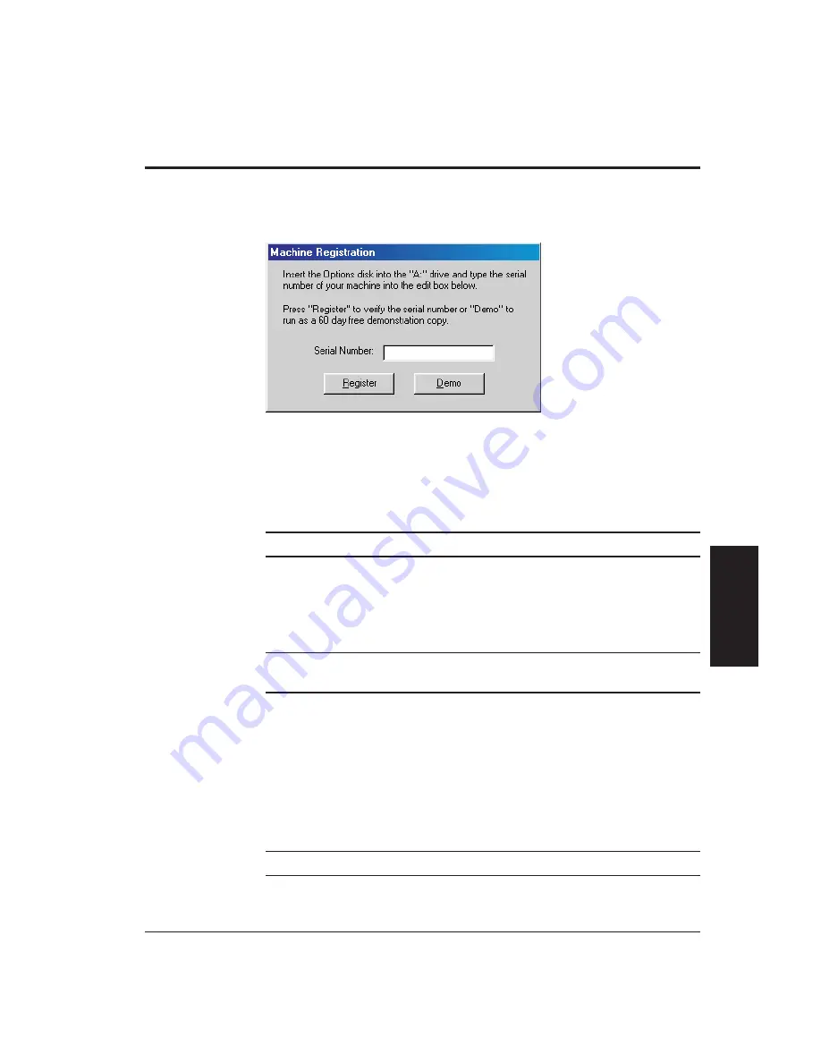
When you initially start Scan-X, the software displays the Machine Registration
dialog box, which prompts you to register the software. You can register Scan-X
now or later.

To register Scan-X

now

, follow the steps below.

1.

Insert the supplied Options disk into the floppy drive.

2.

Enter the serial number of your Cobra (for example, CB1105) in the

Serial

Number

box.

Note:

The serial number is located on top of the unit.

3

Click on the

Register

button.

To register Scan-X

later

, simply click on the

Demo

button to run Scan-X as a

demonstration copy, and register at a later time.

Note:

Scan-X comes with a 60 day trial period. After the trial period expires,

you need to register Scan-X in order to continue using the software.

When you are ready to register Scan-X, follow the steps below.

1.

In Scan-X, select

Register Software

in the

Help

menu.

The Machine Registration dialog box is displayed (see above).

2.

Insert the supplied Options disk into the floppy drive.

3.

Enter the serial number of your Cobra (for example, CB1105) in the

Serial

Number

box.

Note:

The serial number is located on top of the unit.

4.

Click on the

Register

button.

Installation and Setup

2-31

Installation

and

Setup

Summary of Contents for Cobra DRS-300

Page 1: ......

Page 2: ...Safety v Laser Safety Markings vi For More Laser Safety Information vi Electrical Safety vii Power and Grounding vii Servicing vii Liquids vii Accessories viii Unsafe Operating Environments viii Medi...

Page 3: ...edure 2 15 Installing Scan X 2 19 Installing on Windows 98 Second Edition Systems 2 19 Installing on Windows 2000 Systems 2 23 Setting the Parallel Port Address and Mode 2 28 Enabling Scan X 3D Mode 2...

Page 4: ...eo Camera Option 4 8 Removing a Sensor 4 8 Mounting a Sensor 4 9 Section 5 Adjusting the Sensor Mounting Pad Rotational Alignment 5 1 Vertical Adjustment 5 4 Section 6 Troubleshooting Appendix A Setti...

Page 5: ...This page was left blank intentionally Cobra Laser Profile Scanner Users Guide...

Page 6: ...is manual outlines the documentation conventions used in this manual and provides information regarding customer service For Your Safety provides an overview of necessary safety precautions to be obse...

Page 7: ...nvolved in the installation and or operation of your Cobra Related Publications In addition to this manual QVI may provide the following documentation related to Cobra Cobra Certification Reference Gu...

Page 8: ...pe Style or Symbol Used for Examples and Explanations Bold or italic Emphasized words Do not repeat this step Select the highest magnification level Bold sans serif typeface Commands to be typed Keys...

Page 9: ...Alerts you to the potential for damage to the components of Cobra Special instructions may be included for minimizing this risk Note Provides additional information related to the topic being discuss...

Page 10: ...obra Digital Range Sensors DRS use a laser diode as the laser source DRS laser energy is not dangerous to exposed skin However if viewed directly or from a reflection of a specular mirror like surface...

Page 11: ...er Symbol IEC 825 Laser Safety Classification CDRH Laser Safety Classification Laser Aperture Warning For More Laser Safety Information For more information on laser safety contact the Laser Institute...

Page 12: ...supplied with your Cobra If you must use an extension cord make sure it is grounded and is of the proper type and wire gage Do not operate your Cobra if the power cord is damaged Position the power c...

Page 13: ...red Medical Do not operate your Cobra in hospitals clinics or laboratories where sensitive patient monitoring equipment may be affected Radioactive Nuclear Your Cobra s electronics are not radiation h...

Page 14: ...s printed inks and paper surfaces milled surfaces membranes and coatings It is also excellent for measuring flex circuits epoxy dots thick film and solder paste Cobra 2D can be used on a benchtop moun...

Page 15: ...Components Figure 1 1 shows the various components of Cobra 2D See the table that starts on page 1 4 for information about the component functions 1 2 Introduction Figure 1 1 Cobra 2D Components...

Page 16: ...Figure 1 2 shows the various components of Cobra 3D See the table that starts on page 1 4 for information about the component functions Introduction 1 3 Introduction Figure 1 2 Cobra 3D Components...

Page 17: ...t surface Locking Knob Locks the Z axis slide in position Sensor Mounting Pad Supports the sensor on the end of the stage arm Thumb Wheel Raises and lowers the back of the main unit to level Cobra by...

Page 18: ...ED Indicates power is available to the sensor illuminates when Scan X software is active Laser LED Illuminates to indicate laser is taking height measurements LCD Screen Displays a live video image of...

Page 19: ...0 Width 51 0 cm 20 0 Height 39 0 cm 15 4 Weight 80 kg 175 lbs Travel Maximum Y axis scan length 50 mm 2 0 Maximum X axis scan length only applies to Cobra 3D 100 mm 4 0 Z axis adjustment range 50 mm 2...

Page 20: ...ons Figure 1 4 shows the various dimensions of the Cobra main unit Introduction 1 7 Introduction N Distance from the laser sensor to the target in the middle of the capture range Figure 1 4 Cobra Dime...

Page 21: ...ptimized for use with Cobra If you are supplying your own computer it will need to be configured described later and must meet the following minimum requirements Pentium III 500 Mhz processor CD ROM d...

Page 22: ...Z slide to fit a specific application if the slide cannot be moved into the desired position using the Focus knob For example a tall part may require more working clearance thereby necessitating a hig...

Page 23: ...and mounting the laser sensor onto the unit is outlined below Tools and Materials Required To unpack and set up your Cobra 2D system you will need the following 3 mm hex key Allen wrench Utility knife...

Page 24: ...ntil a machinist square or other quality square tool rests squarely on the sensor mounting pad as shown in Figure 2 1 below Note You may need to re level Cobra once the unit is operational in order to...

Page 25: ...y over the mounting holes see Figure 2 2 below Note Mount the sensor so that the laser sensor connector is on the left side of the sensor as shown in Figure 2 2 6 Insert the three mounting screws into...

Page 26: ...r cord into the power cord receptacle on the back panel of Cobra see Figure 2 3 and connect the male end into a properly configured outlet 11 If you did not purchase the Factory supplied Computer opti...

Page 27: ...ers Tools and Materials Required To mount the video camera and LCD screen assemblies onto your Cobra you will need the following 2 mm hex key Allen wrench 3 mm hex key Allen wrench 5 32 hex key Allen...

Page 28: ...the mounting plate to avoid damaging either wire 4 Place the DRS 300 or DRS 500 laser sensor on a flat surface label side up Then set the camera mounting plate and attached camera on the front of the...

Page 29: ...arefully pick up the camera mounting plate and laser sensor and then position and hold them on the sensor mounting pad Use the two positioning pins on the sensor mounting pad to align the sensor and c...

Page 30: ...ert the other two partially threaded screws into the upper two screw holes in the camera mounting plate and sensor Then use a 3 mm hex key Allen wrench to tighten the screws firmly see Figure 2 8 Inst...

Page 31: ...e Connections After mounting the camera and LCD screen assemblies follow the steps below to make the necessary cable connections 1 Locate the Camera and LED Power cable and then connect J2008 to the L...

Page 32: ...wer cable Connect the male end to the Cobra back panel see Figure 2 12 Part A and connect the female end to the back of the LCD screen see Figure 2 12 Part B Installation and Setup 2 11 Installation a...

Page 33: ...sensor cable from the top of the sensor while power is applied to Cobra Doing so can seriously damage the sensor 5 Connect the laser sensor cable to the top of the sensor as shown in Figure 2 14 on th...

Page 34: ...and connect the male end into a properly configured outlet 10 If you did not purchase the Factory supplied Computer option install the Scan X software onto the associated computer described later in t...

Page 35: ...ou will need the following Fork lift or pallet jack Power or manual hoist capable of lifting 80 kg 175 lbs Pair of diagonal cutters Parallel cable Heavy duty desk workbench table or other surface see...

Page 36: ...and ready to be connected to Cobra 1 Use a fork lift or pallet jack to move the pallet containing Cobra 3D and accessories to the installation site The metal bands that bind the shipment are under con...

Page 37: ...her and shipped on a smaller pallet The plastic bands that bind the Cobra 3D shipping carton are under considerable tension and may recoil unpredictably when cut 5 Use a pair of diagonal cutters to cu...

Page 38: ...raight up When lifting flex your knees not your back to avoid back injury Avoid pinching your fingers between the granite and work bench when lowering Cobra Do not attempt to lift Cobra by the handle...

Page 39: ...eceptacle on the Cobra back panel see Figure 2 18 and connect the male end into a properly configured outlet 15 If necessary plug the Motor cable into the AUX AXIS port on the Cobra back panel see Fig...

Page 40: ...n procedure for Windows 2000 systems Installing on Windows 98 Second Edition Systems To install the Scan X software on a Windows 98 Second Edition system follow the steps below 1 Turn on your computer...

Page 41: ...button to continue The system displays the Choose Destination Location dialog box 6 If you agree with the recommended Destination Folder shown at the bottom of the dialog box click on the Next button...

Page 42: ...ype a new folder name or select a folder in the Existing Folders list Then click on the Next button to continue The system displays the Start Copying Files dialog box 8 The system prompts you to verif...

Page 43: ...am Scan X automatically places an icon on the desktop of your computer Note We recommend restarting your computer at this time to ensure that Scan X installs properly Important Before you can use your...

Page 44: ...re installs properly 2 Insert the Scan X installation CD ROM into your system CD drive 3 Click on Start Then highlight and select Run The Run dialog box is displayed 4 Type d or the letter of your CD...

Page 45: ...Welcome to the InstallShield Wizard for Scan X dialog box continue with Step 9 of this procedure 5 Click on Start Then highlight and select Run The Run dialog box is displayed 6 Type c ZCSetup exe in...

Page 46: ...click on the Next button The system displays the Choose Destination Location dialog box 10 If you agree with the recommended Destination Folder shown at the bottom of the dialog box click on the Next...

Page 47: ...t folder type a new folder name or select a folder from the Existing Folders list Then click on the Next button to continue The system displays the Start Copying Files dialog box 12 The system prompts...

Page 48: ...utomatically places an icon on the desktop of your computer Note We recommend restarting your computer at this time to ensure that Scan X installs properly Important Before you can use your Cobra syst...

Page 49: ...upplied computer you can skip this section the parallel port on your system was set at the factory The parallel port mode needs to be set to Bi directional mode For on board parallel ports this is don...

Page 50: ...uration Settings file SCANX INI located in the following default folder C Program Files Scan X Config Assign the port address to the appropriate parallel port being used by typing in either the port n...

Page 51: ...urchased with the Factory supplied Computer option you can skip this section because Scan X 3D mode was enabled at the factory To enable Scan X 3D mode follow the steps below 1 Open the SCANX INI file...

Page 52: ...ly click on the Demo button to run Scan X as a demonstration copy and register at a later time Note Scan X comes with a 60 day trial period After the trial period expires you need to register Scan X i...

Page 53: ...This page was left blank intentionally 2 32 Installation and Setup...

Page 54: ...r 2 Turn on your Cobra The power switch is located in the upper right corner on the Cobra back panel as shown in Figure 3 1 3 Access Scan X by using one of the following methods Double click on the Sc...

Page 55: ...Screen Layout 2D Mode The Scan X screen in 2D mode is divided into the areas and windows displayed below 3 2 Getting Started...

Page 56: ...Contents list or Index list to find the topics you want to view See How to View Help Topics on the following page for more information In addition to the on line Help topics you can also view example...

Page 57: ...on the Display button The selected topic is then displayed as shown on the following page To view a topic from the Index list follow the steps below 1 Access the Scan X on line Help as described on th...

Page 58: ...ht to view the rest of the text You can jump to any topic that is shown in green simply by clicking on the link If you wish to view a Help topic and use the software at the same time for example when...

Page 59: ...counter clockwise to lower it make sure the Locking knob is not tightened The Locking Knob is located on the left side of the sensor mounting pad as shown in Figure 3 1 and is used to lock the Z axis...

Page 60: ...rofile Collect height and length measurement results Save the measurement results from the laser scan View the measurement results from the laser scan This tutorial is also documented in the Scan X on...

Page 61: ...system 4 Click the Laser Locator button to turn off the Laser Locator This activates the Laser Focus bar The Laser Focus bar is located on the left side of the Profile View below the Laser Locator but...

Page 62: ...d position field for a 3D scan as shown below For a 3D scan also enter a value of 5 in the X end position field 11 Enter a value of 0 05 in the Step box see below For a 3D scan enter a value of 0 50 i...

Page 63: ...column as shown below 16 Click and drag the reference cursor boundaries so that the cursor includes a flat area next to the column as shown below The height of the column in the primary cursor is dis...

Page 64: ...e Save icon or select Save in the File menu The Save File dialog box is displayed 22 Select sc6 in the Save as Type list 23 Select the folder where you want to save the file 24 Enter a filename for ex...

Page 65: ...needed to obtain a valid height reading The acceptable values for this setting are from 0 000002 to 0 065535 seconds The default value is 0 005 which provides acceptable results for most surfaces Not...

Page 66: ...eshold The threshold value is represented by a red line in the Sensor Settings window Data below the bar is eliminated from the evaluation and data above the bar is included The sensor spot height cal...

Page 67: ...This page was left blank intentionally 3 14 Getting Started...

Page 68: ...ging sensors on Cobra systems not equipped with the video camera option starts on page 4 8 Be sure to follow the procedure that applies to your system DRS Models There are four different sensor models...

Page 69: ...0 lasers Removing the Video Camera Assembly and Sensor To remove the video camera assembly and sensor follow the steps below You will need 2 mm and 3 mm hex key Allen wrenches 1 Power down your Cobra...

Page 70: ...Figure 4 1 The camera is still attached to the mounting plate via the LED power wires red and black These two wires are fairly delicate Therefore keep the camera close to the mounting plate to avoid d...

Page 71: ...key Allen wrench to remove the screw See Figure 4 2 6 Hold the camera assembly mounting plate and sensor as you remove the other two sensor mounting screws see Figure 4 3 Use a 3 mm hex key Allen wren...

Page 72: ...2 Refer to Figure 4 4 on the following page and perform the following steps a Carefully swing the camera assembly to the right or left to reveal the lower screw hole in the camera mounting plate Then...

Page 73: ...rews removed in Step 4 of the previous procedure to resecure the camera to the camera mounting plate see Figure 4 5 4 6 Swapping Sensors Figure 4 4 Installing the Camera Mounting Plate and Sensor Figu...

Page 74: ...isconnect the laser sensor cable from the sensor while power is applied to Cobra Doing so could seriously damage the sensor 5 Connect the laser sensor cable to the top of the sensor 6 Check the camera...

Page 75: ...stem Never connect or disconnect the laser sensor cable from the sensor while power is applied to Cobra Doing so could seriously damage the sensor 2 Disconnect the laser sensor cable from the top of t...

Page 76: ...sor onto your Cobra system follow the steps below You will need a 3 mm hex key Allen wrench 1 Power down your Cobra system 2 Mount the laser sensor onto the sensor mounting pad Use the two positioning...

Page 77: ...Never connect or disconnect the laser sensor cable from the sensor while power is applied to Cobra Doing so could seriously damage the sensor 4 Connect the sensor cable to the top of the sensor see F...

Page 78: ...ction 2 for more information Consult your local authorized sales representative for more information on field certification of your Cobra system Rotational Alignment The rotational alignment procedure...

Page 79: ...Place a machinist square or other quality square tool on the work surface parallel to the X axis and observe whether or not both of the positioning pins on the sensor mounting pad make contact with th...

Page 80: ...two screws loosened in Step 5 8 Verify that both positioning pins still make contact with the square tool after tightening the sensor mounting pad screws If both pins touch the square tool go to Step...

Page 81: ...following procedure will disrupt the alignment and void the certification of your Cobra system 1 Remove the DRS laser sensor as described in Section 4 2 Loosen the Locking knob see Figure 5 3 3 Twist...

Page 82: ...ep 4 into the sensor mounting pad access holes and tighten Use a 3 mm hex key Allen wrench 8 Perform Steps 4 through 8 of the Rotational Alignment procedure described previously in this section to ver...

Page 83: ...This page was left blank intentionally 5 6 Adjusting the Sensor Mounting Pad...

Page 84: ...cle on the Cobra back panel Cobra power cord is not connected to the main power source Connect the Cobra power cord to the main power source Faulty wall outlet Use different wall outlet Repair current...

Page 85: ...creen Power cable is disconnected Verify that the LCD Screen Power cable is connected to the back of Cobra and the top of the camera see Figure 2 12 Faulty LCD screen Swap suspected faulty LCD screen...

Page 86: ...connection Dirty sensor lenses Check lenses for dirt clean if necessary Faulty sensor Swap suspected faulty sensor for known good one replace if necessary Sensor does not turn on and or the laser indi...

Page 87: ...This page was left blank intentionally 6 4 Troubleshooting...

Page 88: ...g the scan in real time On line Help See the topic How to Scan a Part If you perform a laser scan and are unable to see the scan in real time you may need to reduce one of the following display proper...

Page 89: ...art menu and then double click on Display in the Control Panel window to display the Display Properties window 3 Click on the Settings tab Something similar to the following is displayed 4 In the Colo...

Page 90: ...to the left one setting 7 Click on OK 8 Restart your computer 9 Access Scan X and perform a laser scan On line Help See the topic How to Scan a Part for more information If you are still unable to see...

Page 91: ...This page was left blank intentionally A 4 Setting the Display Properties...

Page 92: ...part Observe the image of the part on the LCD screen On line Help See the topic How to Focus the Sensor for more information If the image is sharp and in focus stop here You do not need to perform the...

Page 93: ...sharp and in focus Then without moving the camera retighten the camera collar firmly Important After tightening the camera collar verify that the image on the LCD screen is still in focus If it is not...

Page 94: ...rews securing the camera cover to the camera assembly see Figure 2 4 on page 2 6 4 Align the camera by moving it slightly as described below while observing the position of the laser spot on the LCD s...

Page 95: ...Reinstall the camera cover This completes the procedure for aligning the video camera on your Cobra system to the DRS laser sensor B 4 Focusing and Aligning the Camera Figure B 2 Camera Alignment Scre...

Page 96: ...s 1 8 D Dimensions 1 6 1 7 Display properties A 1 Reducing the hardware acceleration A 3 Reducing the number of colors A 2 Document Conventions iii Organization i DRS models 4 1 DRS 2000 4 1 DRS 300 4...

Page 97: ...ing pad 1 4 5 1 N Nuclear viii O OGP Customer Service iv Operating environment 1 6 Optimizing laser settings 3 12 Organization i P Parallel port 1 4 Setting the address and mode 2 28 Power cord recept...

Page 98: ...2D mode 3 2 Screen layout 3D mode 3 3 Tutorial 3 7 Screen layout 2D mode 3 2 3D mode 3 3 Setting the parallel port address and mode 2 28 Settings 3 12 Maximum exposure 3 12 Threshold 3 13 Special sym...

Page 99: ...rt of QVI Caution This equipment generates uses and can radiate radio frequency energy and if not installed and used in accordance with this documentation may interfere with radio communications Opera...

Page 100: ......

Reviews: