Danger of electric shock
Danger to life due to electric current!
Before service work is started, the boiler has to be de-energised
and secured from accidentally being switched back on.
The following steps describe how to change the ignition electrodes:
1. Loosen ignition cable
2. Loosen nuts and pull the ignition electrode block with seal out of the
burner cover
Note
The illustration shows removal of the ignition electrodes from the
EC four 125 kW - 170 kW. Removal of the ignition electrodes from
the EC four 215 kW - 300 kW is carried out in the same way.
3. Insert the new ignition electrode block with seal and fasten with nuts
Note
Please note: The spacing and installation positions specified in the
section
Electrode spacing and installation locations
must be hee
ded.
4. Reconnect the ignition cable
For more information, see
Electrode spacing and installation locations, page 137
10.3.9 Checking the ionization electrode
For measurement of the ionization current, pull plug from the gas burner
control and connect ammeter between plug and electrode. Measurement
must be carried out at full load and part load.
Danger of electric shock
Danger to life due to electric current!
Do not touch plug contacts during the ignition process!
The ionization electrode must always be in contact with the flame. During
burner operation, the measured ionization flow must display the following
values:
at minimum power > 5 µA DC (switching threshold at 0.7 µA DC)
at maximum power > 10 µA DC
If these values are not reached, the ionization electrode must be replaced.
10.3.1
0
Changing the ionization electrode
Danger of electric shock
Danger to life due to electric current!
Before service work is started, the boiler has to be de-energised
and secured from accidentally being switched back on.
The following steps describe how to change the ionization electrode:
1. Loosen ionization line
RA-0000240
2
10 Maintenance
136
7636047 - 02 - 24082015
Summary of Contents for eurocondense four 125 kw
Page 19: ...3 2 6 Wiring diagram Fig 3 Wiring diagram 3 Technical specifications 7636047 02 24082015 19 ...
Page 40: ...Fig 22 Legend for application examples part 2 5 Before installation 40 7636047 02 24082015 ...
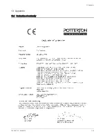
Page 143: ...13 Appendix 13 1 Declaration of conformity 13 Appendix 7636047 02 24082015 143 ...
Page 146: ...Index 146 7636047 02 24082015 ...
Page 148: ...7636047 02 24082015 ...


