


L-827e.A3 phyCORE-i.MX 6UL/ULL Hardware Manual
© PHYTEC Messtecknik GmbH
52
TABLE 22: I2C Interface Signal Location
Pin #
Signal
ST
Voltage Domain
Description
60
X_I2C1_SCL
I/O
VDD_3V3
I2C1 clock
61
X_I2C1_SDA
I/O
VDD_3V3
I2C1 data
11.6 Audio Interfaces
11.6.1 I
2
S (SAI)
The Synchronous Audio Interface (SAI) of the phyCORE
‑
i.MX 6UL/ULL is a full-duplex, serial interface that allows
communication with a variety of serial devices, such as standard codecs, digital signal processors (DSPs),
microprocessors, peripherals, and popular industry audio codecs that implement the inter-IC sound bus standard
(I
2
S) and Intel AC’97 standard. The i.MX 6UL/ULL provides up to three instances of the SAI module.
The main purpose of this interface is to connect to an external codec, such as I
2
S. The Synchronous Audio Interface
is intended to be used in synchronous mode. Hence, the receive data timing is determined by SAI2_TX_BCLK and
SAI2_TX_SYNC. The five signals extending from the i.MX 6UL/ULL's SAI2 module to the phyCORE-Connector are
SAI2_RX_DATA, SAI2_TX_BCLK, SAI2_MCLK, SAI2_TX_SYNC, and SAI2_TX_DATA.
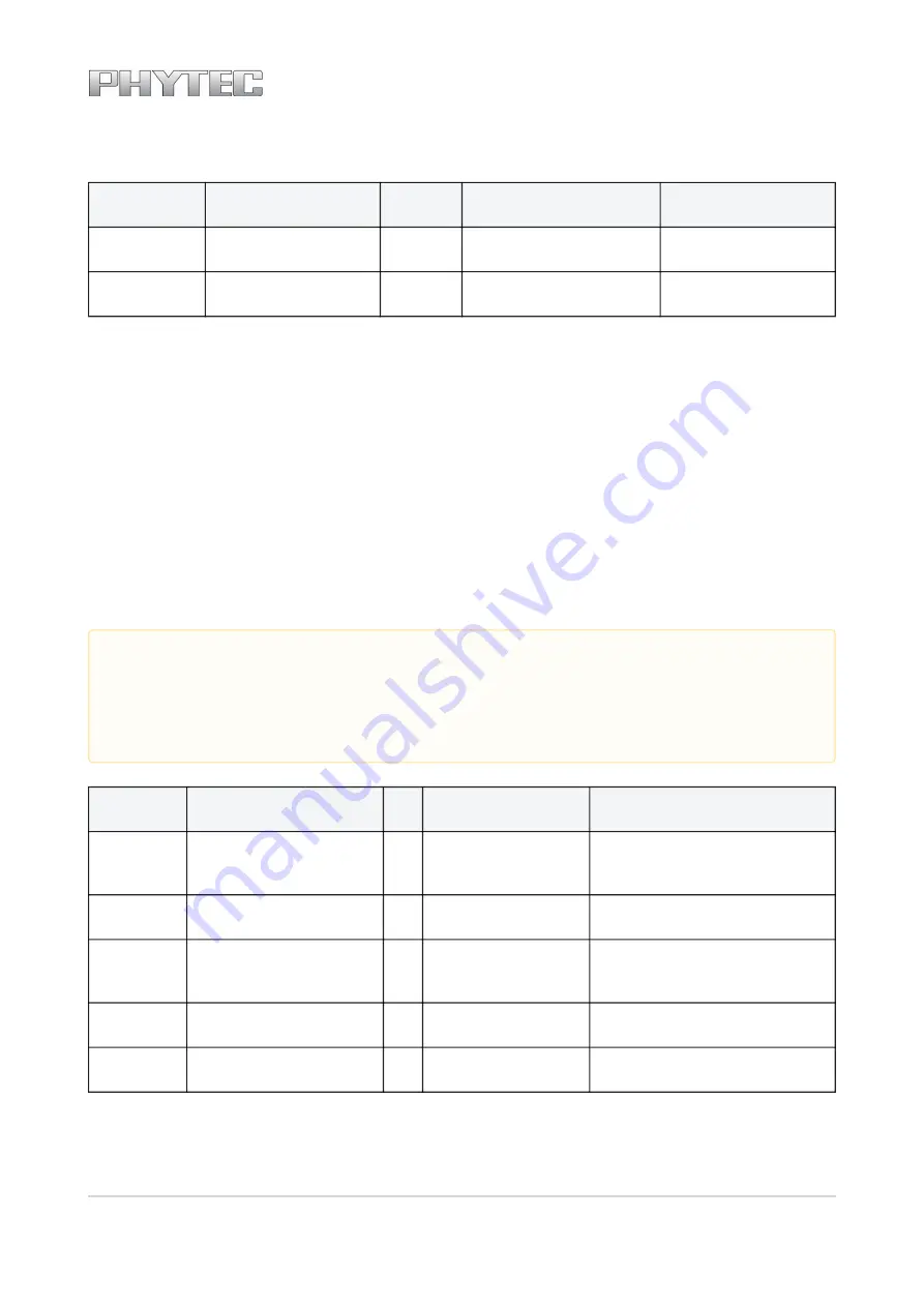
TABLE 23: I2S Interface Signal Location
Pin #
Signal
ST
Voltage Domain
Description
79
X_JTAG_TDI/SAI2_TX_BCLK
O
VDD_3V3
SAI2 transmit bit clock
(SAI2_TX_BCLK)
80
X_JTAG_TCK/SAI2_RXD
I
VDD_3V3
SAI2 receive data (SAI2_RXD)
82
X_JTAG_TDO/
SAI2_TX_SYNC
O
VDD_3V3
SAI2 transmit frame
synchronization (SAI2_TX_SYNC)
83
X_JTAG_TMS/SAI2_MCLK
O
VDD_3V3
SAI2 master clock (SAI2_MCLK)
84
X_nJTAG_TRST/SAI2_TXD
O
VDD_3V3
SAI2 transmit data (SAI2_TX_DATA)
Note
Use of the i.MX 6UL/ULL's JTAG interface pins for the I
2
S interface is the default muxing option within the
BSP delivered with the phyCORE
‑
i.MX 6UL/ULL. Please refer to the
i.MX 6UL/ULL Reference Manual
for more
muxing options about this interface or consider that fact in the carrier board design if a JTAG interface is
also to be implemented.