FL20-C Series
111
(1)When 2008h-31h=1,the H group parameters can be set. After electrical degree identification
is finished, the installation angle of the encoder is saved in 2006h-13h. Please refer to chapter 6
for operating method of electrical degree identification.
(2) Different motor parameter corresponds to different servo motor, make sure the parameters
are in accordance with the motor’s before using.
(3) Change the value of 2006h-48h according to heat radiation of the motor. It can adjust the
motor overload protection time early or delayed. The higher the parameter value is, the longer
overload protection time is.
(4) Do not modify motor parameters set by the manufacturer .If the system is damaged because
user sets the wrong motor parameters or use non-standard motor, user should be response for
the consequence.
2
)
Switching the Servo motor Rotation Direction
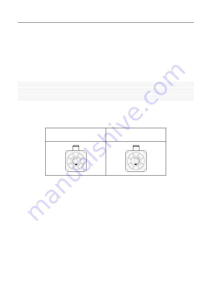
The default setting for “forward rotation” is counterclockwise as viewed from the servo motor
shaft. The mfr’s value of 2000h-02h.Y is 1. When 2000h-02h.Y is set to 0, the forward rotation
is clockwise as viewed from the servo motor shaft.
2000h-02h.Y =1
,
forward
rotation is counterclockwise.
2000h-02h.Y =0, forward
rotation is clockwise.
3
)
Holding brake setting
The holding brake is used when the servo motr controls a vertical shaft. The servo motor with
brake prevents the movable part from shifting due to gravity when the power supply fails. The
holding brake function is only suitable for servo motor with brake.
a)
Wiring of holding brake


