background image

Managing Multiplexers

1-69

6800-A2-GB21-10

August 1994

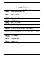
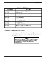
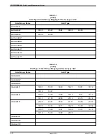
Table 1-6

Alert Groups for Device Type 

ntwk

Alert Group Name

Type of Alerts

ntwk-event#

Miscellaneous events and unmapped events.

ntwk-facerr#

Facility error events.

ntwk-noderr#

Node-level error events.

ntwk-callst#

Call-status events.

ntwk-nodst#

Node-level status events.

ntwk-facstt#

Facility statistics events.

ntwk-nodstt#

Node-level statistics events.

ntwk-sdlstt#

SDL statistics events.

ntwk-usrevt#

User-defined event groups.

ntwk-alarm#

Miscellaneous alarms and unmapped alarms.

ntwk-usralm#

User-defined alarm groups.

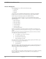
ACCULINK Event to NMS Alert Group Assignments

Each ACCULINK event is assigned to one of the predefined NMS alert groups by the UNIX text
file EToAMapping which resides in the directory /usr/nms/RNMS/ANM/data/backup. A user may
view the file to determine the current assignments and may also edit the file to create new
assignments. Default assignments are given in Tables 1-7 through 1-10. Procedures for viewing or
editing the file are given later.

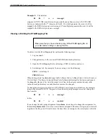
WARNING

Before viewing or editing the EToAMapping file, you must make
a copy of the file on your disk and print out a hardcopy of the
file to protect the file’s integrity. This is an important
precautionary step.

Summary of Contents for COMSPHERE 6800 Series

Page 1: ...You have accessed an older version of a Paradyne product document Paradyne is no longer a subsidiary of AT T Any reference to AT T Paradyne is amended to read Paradyne Corporation...

Page 2: ...E 6800 Series Network Management System Multiplexer Management and Configuration Guide Document No 6800 A2 GB21 10 NOTE This document supports Release 4 2 or greater of 6800 Series NMS Paradyne Printe...

Page 3: ...N ACCULINK is a registered trademark of AT T COMSPHERE is a registered trademark of AT T DATAPHONE is a registered trademark of AT T COPYRIGHT E 1994 AT T Paradyne Corporation All rights reserved This...

Page 4: ...ied service personnel 6 General purpose cables are provided with this product Special cables which may be required by the regulatory inspection authority for the installation site are the responsibili...

Page 5: ...COMSPHERE 6800 Series Network Management System C August 1994 6800 A2 GB21 10 Notices...

Page 6: ...rface 1 21 DS1 Channel Modules 1 24 Network Administration Ports NAPs 1 24 Attribute Configuration 1 25 Supervisory Data Links SDLs 1 26 Configuring Local Links 1 30 Configuring Channel Groups 1 32 Pe...

Page 7: ...e Specification Dialog Window 1 52 1 6 Destination Node s Window 1 55 1 7 Trimming Options Window 1 57 1 8 Confirmation Window 1 58 1 9 Node Information Window 1 60 1 10 Entry Information Window 1 61...

Page 8: ...Device Type ntwk 1 69 1 7 Alert Type to Alert Group Mapping for Device Type swtch 1 70 1 8 Alert Type to Alert Group Mapping for Device Type ntwk 1 72 1 9 Alert Type to Alert Group Mapping for Device...

Page 9: ...COMSPHERE 6800 Series Network Management System iv August 1994 6800 A2 GB21 10 This page intentionally left blank...

Page 10: ...anual Chapter 1 Managing Multiplexers provides an overview of the products and features supported and the information necessary to manage a multiplexer network with the 6800 Series NMS Chapter 2 Confi...

Page 11: ...d by the entry PRESS indicates when the entry is a special key usually the Enter key Related Documents 6800 A2 GB31 COMSPHERE 6800 Series Network Management System Communications Products Support Comm...

Page 12: ...18 Alarm Severity Reporting Configuration 1 18 Event Reporting Configuration 1 19 Configuring the Physical T1 Link Interface 1 21 Link Redundancy 1 21 Service States 1 22 Line Encoding Options for 731...

Page 13: ...ting a Routing Table 1 54 Editing a Routing Table 1 54 Trimming a Routing Table 1 56 Undoing Editing Changes 1 58 Deleting a Routing Table 1 58 Saving a Routing Table 1 59 Printing 1 59 Obtaining Node...

Page 14: ...connections between the NMS host computer and the ACCULINK network are completed you must configure the ports on one or more of these local multiplexers to send and receive specific information about...

Page 15: ...ts Alternatively you can use two or three nodes for the ports since all three ports do not need to be on the same node In addition to configuring the port s on the 719 NETWORKER and the 74x multiplexe...

Page 16: ...and to the network to obtain the node s model number version number feature package and product type series 700 for the chassis and CPU types listed below If the data and node are accessible to the NM...

Page 17: ...r 719 719 ntwk 719 721 719 ntwk 721 722 719 ntwk 722 723 719 ntwk 723 725 719 ntwk 725 724 735 56K mux 735 724 735 T1 mux 735 731 740 T1 mux 731 735 735 56K mux 735 735 735 T1 mux 735 741 735 56K mux...

Page 18: ...sing the Create User Profile crup or Edit User Profile edup commands respectively from the Manager task Multiplexer Security through the NMS External Systems Interface The ACCULINK multiplexers in the...

Page 19: ...rofile the NMS returns a message indicating that channel groups passing through the node must be deleted before the profile can be deleted Successfully adding deleting and editing device profiles caus...

Page 20: ...plexers always imply the 741 and 742 multiplexer also unless explicitly stated otherwise References to 74x 56K multiplexers always imply both the 742 chassis and the 740 chassis unless explicitly stat...

Page 21: ...Create Site Profile crsp and Create Vendor Profile crvp commands These profiles are used to describe and place the site location for each node for use by the network map and to describe and store inf...

Page 22: ...r a value from 1 14 Port Use this field to specify the module s port that is functioning as the facility s termination point Enter a value from 1 6 Id This field is automatically filled in by the NMS...

Page 23: ...figuring an Existing Network for a New NMS For migrating from a previous NMS release go to Configuring an Existing Network with a Migrated NMS Configuring a New Network with a New NMS To configure a n...

Page 24: ...ultiplexer to match the password you entered through this command If the passwords do not match NMS cannot communicate with the multiplexers 3 Execute the Create Device Profile crdp command to create...

Page 25: ...s are sent to the NMS for centralized monitoring To download network time from the NMS to the nodes To set configurations for each node s message log alarm severity reporting parameters and statistics...

Page 26: ...configure the multiplexer cut through by assigning your own name for the cut through session to the proper port group See the COMSPHERE 6800 Series Network Management System Core Command Reference Ma...

Page 27: ...port rate To configure the attribute names for each node To modify any of the default values for these parameters 8 As applicable perform Steps 9 through 11 9 Upload physical attributes using the Acqu...

Page 28: ...CPUs and TSIs channel hardware such as channel modules and channel interface modules physical 56K 64K or T1 links such as DS1 modules and aggregate link modules channels channel groups NAPs and SDLs T...

Page 29: ...e A 745 multiplexer can be equipped with either one or two for optional redundancy time slot interchange TSI modules The CPU monitors the active TSI If a failure is detected and the node is equipped w...

Page 30: ...node you can designate the alarm relay or audible alarm that is activated when an alarm occurs on a T1 link a control processor a TSI clock etc Using this command each alarm class can be assigned one...

Page 31: ...arded to a multiplexer s event log 1 and 3 and designate the physical location to which events are to be sent Configure event log 2 to determine what events will be sent from a node to the 6800 Series...

Page 32: ...inks on a Series 700 to Series 700 facility or you can configure a single link at a time The NMS can verify that the configuration of the links on each end of the T1 facility are compatible The facili...

Page 33: ...ion ACAMI is a method of line encoding that allows clear channel data to be sent over an AMI ZCS encoded T1 line by forcing every other time slot in the T1 to a constant value so that 16 consecutive z...

Page 34: ...e T1 link contains both ACAMI and non ACAMI time slots after the change request the request will not be accepted Use the Logical Link Summary lls command to verify this To correct this situation execu...

Page 35: ...rvice The following commands are related to the DS1 channel modules Change DS 1 Channel Module Configuration chdcmc Display DS 1 Channel Module Configuration dsdcmc DS 1 Channel Loopback dcl DS 1 Chan...

Page 36: ...for command and event datagram use Refer to Chapter 2 for details on configuring this NAP type The following commands are related to NAPs Change Network Administration Port Configuration chnapc Displa...

Page 37: ...o the 6800 Series NMS with the Acquire Physical Attributes acpa command and logical attributes with the Acquire Logical Link acll command if you have already defined attribute characteristics before i...

Page 38: ...pports only one embedded SDL per physical T1 NAP tail circuits see synchronous SDL below can be used to provide supervisory connectivity from the central site 740 to the other remote 740s external NAP...

Page 39: ...to configure as either embedded SDL or synchronous SDL by selecting yes in the desired time slot Only one embedded SDL can be configured per link but multiple synchronous SDLs are permitted 4 For sync...

Page 40: ...Slot Format field displays filler the time slot is being used as filler byte data for ACAMI channels You cannot use the Change SDL Configuration chsdlc command to reconfigure this time slot Either yo...

Page 41: ...acteristics before you can configure the time slot for SDL The following commands are related to SDLs Change Supervisory Data Link Configuration chsdlc Display Supervisory Data Link Configuration dssd...

Page 42: ...to 6 characters including the mandatory prefix LL Logical link names can be up to 18 characters including the mandatory prefix ll Time Slots Characteristics and Logical Attributes You assign a capaci...

Page 43: ...te Break Logical Link Connection brllc command or the Make Logical Link Connection mkllc command The Logical Link Summary lls command allows you to view logical link connections by node and attribute...

Page 44: ...same When channel group transactions are done through the multiplexer menu system only the multiplexer s database records the transactions The data is not recorded on the NMS database which can resul...

Page 45: ...nel Group crcg command determine if a channel group should be routed only over routes that meet attribute requirements For example you could specify that channel group abc can only traverse paths that...

Page 46: ...ific types of channels that are network compatible Network compatible channels are channels whose bandwidth minus the channel group framing bits equals the size of one DS0 Placing these channels into...

Page 47: ...e routed over an alternate route that does not avoid The channel group will not be routed over any path that possesses this attribute ignore The channel group will ignore this attribute for routing pu...

Page 48: ...used when channel groups are created deleted or changed using the terminal interface to the multiplexers instead of the 6800 Series NMS In that case when the NMS is bypassed to configure channel group...

Page 49: ...the channel group s capacity The difference is the channel group s available bandwidth 2 Make sure that the channel has two compatible channel endpoints Compatible channel endpoints are any two chann...

Page 50: ...Use the MRT to customize the routing table of each node or use the Change Routing Table chrt command 5 Execute the Change Node Configuration Parameters chncp command to configure event log 2 of the ne...

Page 51: ...o delete any channel group that has the node as an endpoint 2 Execute the Delete Logical Link dlll command to delete any logical link NOTE Steps 3 and 4 as follows should only be done if you want to t...

Page 52: ...a link to a new node and how to add a link to an existing node Adding a Link to a New Node If you are adding a link to a new node the steps described in the Adding a Node section provide the system wi...

Page 53: ...e dlfp command to delete any reference to the facility for the specified link 5 Use the Manage Routing Table Utility to change a routing table at a specific node or execute the Change Routing Table ch...

Page 54: ...ored seconds loop errored seconds loop side signal losses and loop side signal status for each DDS channel DDS Channel Trouble Codes ddsctc Displays the number of key control codes such as the number...

Page 55: ...summary lists the node of a channel the cross connect time slots whether the time slot is being used for SDL logical links or ACAMI filler byte data and the service state Hardware Module Summary hms D...

Page 56: ...ities enhancements include viewing more lines of destination nodes and links at one time and changing routing tables based on hop counts and maximum links per destination node Fallback mechanisms the...

Page 57: ...information viewed in particular areas of the screen see Figure 1 2 Routing Table Information Area Routing Table Editing Area Main Menu Bar Node Selection List Status Message Area Figure 1 2 Manage Ro...

Page 58: ...ing table to either the network or a file Save All is similar to Save except that all loaded routing tables are copied Print Routing Table prints a selected routing table to the system printer Print S...

Page 59: ...en edited the node identifier is displayed in bold Routing Table Editing Area The Routing Table Editing Area see Figure 1 2 is located below the Routing Table Information Area and to the left of the N...

Page 60: ...n for an MRT function that function will obtain or send routing tables from or to the nodes in the network If the function is Generate you must always specify the source as Network To select the netwo...

Page 61: ...esired file name in the list The name appears in the selection area or b Click on the Selection area The I bar appears in the selection area TYPE the desired file name 4 To review the contents of the...

Page 62: ...empty file and can only be a destination for saving a routing table A routing table cannot be retrieved from that new file until a routing table has been saved to it To set a new file as the destinati...

Page 63: ...rt command the new routing table is not downloaded automatically to the specified node Rather it is loaded into the MRT and entered into the Node Selection list The source field must be set to Ntwk pr...

Page 64: ...on Complete The node identifiers are displayed in the Node Selection List Retrieving a Routing Table from the Network Routing tables are stored at the nodes in the network and must be obtained from th...

Page 65: ...n the destination node is deleted The MRT has no explicit Undo command Please refer to the section Undoing Editing Changes Clicking the mouse with the cursor pointing to the link list area selects the...

Page 66: ...uence The I bar appears in the link list area for the entry of the links associated with this destination node 4 TYPE the links associated with the new destination node separate multiple links by comm...

Page 67: ...ined in those tables If the number of links exceeds that limit the MRT cannot save the entire table to the node You can trim routing tables using two methods Trimming by link count reduces the link li...

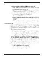
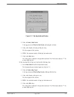
Page 68: ...specified maximum The column contains an for each modified link list To trim a routing table by hop count perform the following steps 1 Select Trim Entries from the Edit pull down menu The Trimming Op...

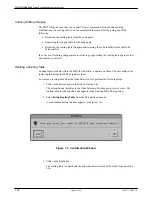
Page 69: ...again are lost and must be re entered Deleting a Routing Table Routing tables are held within the MRT for the utility to operate on them The only method for removing them from the MRT is to delete th...

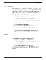
Page 70: ...uting Table Editing Area 3 Click on Save from the Table pull down menu The Status Message area shows Save Complete To save all routing tables loaded in the MRT perform the following steps 1 Set the de...

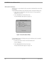
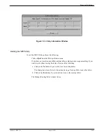
Page 71: ...tifier in the Node Selection List The node identifier is highlighted in inverse video 2 Click on Node Info from the Misc pull down menu The Node Information window appears see Figure 1 9 Figure 1 9 No...

Page 72: ...you have not saved any modified routing tables a dialog window appears asking if you want to quit without saving the tables Do one of the following a Click on the No button if you wish to save the ro...

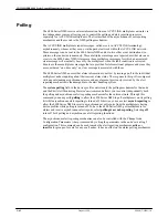
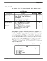
Page 73: ...nodes inquiring about their current alarm status The response to this poll is compared with any outstanding asynchronous alarms and any alarm not previously received by the alert reporting mechanism...

Page 74: ...K network consisting of 40 nodes If the Poll Group Size parameter is set to 5 and the Poll Interval parameter is set to 10 then the 6800 Series NMS will poll five nodes every 10 seconds Nodes are poll...

Page 75: ...SS Return Activating Polling Parameter Changes After the polling parameters have been changed the parameters may be immediately activated without shutting down and restarting the 6800 Series NMS To ac...

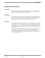
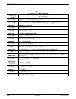
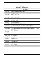
Page 76: ...Guide Alert Groups Tables 1 3 through 1 6 summarize the predefined alert groups established by the 6800 Series NMS for ACCULINK devices The pound sign at the end of each alert group name may be replac...

Page 77: ...ux facstt Facility statistics events mux nodstt Node level statistics events mux sdlstt SDL statistics events mux usrevt User defined event groups mux alarm Miscellaneous alarms and unmapped alarms mu...

Page 78: ...usrevt User defined event groups swtch alarm Miscellaneous alarms and unmapped alarms swtch nmsalm Alarms generated by the ACCULINK Network Management application swtch alink Active link alarms swtch...

Page 79: ...tt Facility statistics events 56mux nodstt Node level statistics events 56mux sdlstt SDL statistics events 56mux usrevt User defined event groups 56mux alarm Miscellaneous alarms and unmapped alarms 5...

Page 80: ...unmapped alarms ntwk usralm User defined alarm groups ACCULINK Event to NMS Alert Group Assignments Each ACCULINK event is assigned to one of the predefined NMS alert groups by the UNIX text file EToA...

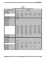
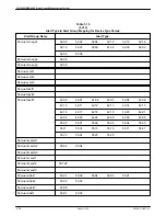
Page 81: ...9 19 48 12 48 19 48 20 48 21 48 23 swtch callst2 19 02 19 09 19 10 19 11 19 13 19 17 21 00 22 00 23 12 23 13 23 14 48 14 48 22 swtch callst3 12 01 13 01 15 00 15 10 17 00 19 00 19 04 19 05 19 06 19 07...

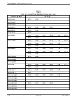
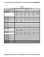
Page 82: ...4 43 05 swtch nmsalm1 swtch nmsalm2 00 02 00 04 swtch nmsalm3 swtch nmsevt1 swtch nmsevt2 00 128 swtch nmsevt3 swtch noderr1 53 01 53 05 53 17 53 18 53 19 53 20 swtch noderr2 53 00 53 14 53 16 swtch n...

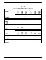
Page 83: ...swtch usrevt1 swtch usrevt2 swtch usrevt3 Table 1 8 1 of 2 Alert Type to Alert Group Mapping for Device Type ntwk Alert Group Name Alert Type ntwk alarm1 ntwk alarm2 ntwk alarm3 ntwk callst1 18 01 18...

Page 84: ...err3 ntwk facstt1 ntwk facstt2 ntwk facstt3 14 05 14 06 14 07 14 08 14 09 14 10 14 11 ntwk noderr1 05 00 ntwk noderr2 11 00 ntwk noderr3 ntwk nodst1 ntwk nodst2 ntwk nodst3 01 00 02 00 03 00 04 02 04...

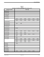
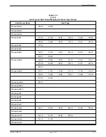
Page 85: ...2 00 63 00 90 00 92 00 96 00 98 00 100 00 mux alink3 64 00 mux callst1 19 01 19 12 19 19 48 12 48 19 48 20 48 21 48 23 mux callst2 19 02 19 09 19 10 19 11 19 13 19 17 21 00 22 00 23 12 23 13 23 14 48...

Page 86: ...tt1 mux facstt2 mux facstt3 42 00 42 01 42 02 42 03 42 04 42 05 42 06 42 10 42 11 42 12 42 13 42 14 42 15 42 16 42 17 42 18 42 19 42 20 42 21 42 22 42 23 42 24 42 25 42 26 43 00 43 01 43 02 43 03 43 0...

Page 87: ...28 53 29 54 00 54 01 54 02 54 03 54 14 mux nodstt1 mux nodstt2 mux nodstt3 55 06 55 07 55 08 55 09 55 10 55 12 mux sdl1 55 18 83 00 mux sdl2 mux sdl3 mux sdlstt1 mux sdlstt2 mux sdlstt3 14 05 14 06 14...

Page 88: ...1 06 56mux alink3 56mux callst1 19 01 19 12 19 19 48 12 48 19 48 20 48 21 48 23 56mux callst2 19 02 19 09 19 10 19 11 19 13 19 17 21 00 22 00 23 12 23 13 23 14 48 14 48 22 56mux callst3 12 01 13 01 15...

Page 89: ...nt1 56mux event2 56mux event3 56mux facstt1 56mux facstt2 56mux facstt3 42 00 42 01 42 02 42 03 42 04 42 06 42 10 42 11 42 12 42 13 42 14 42 15 42 16 42 17 42 18 42 19 42 20 42 21 42 22 42 23 42 24 42...

Page 90: ...27 53 28 53 29 54 00 54 01 54 02 54 03 54 14 56mux nodstt1 56mux nodstt2 56mux nodstt3 55 06 55 07 55 08 55 09 55 10 55 12 56mux sdl1 52 18 83 00 56mux sdl2 56mux sdl3 56mux sdlstt1 56mux sdlstt2 56mu...

Page 91: ...s defined by each device For example the code 80 00 corresponds to CPU Diagnostic Alarm for multiplexers and switches The Device Class field is a single character identifying the general class of devi...

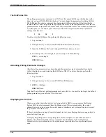
Page 92: ...he NMS alert group swtch noderr2 Example 2 The data line 51 00 m n a alink1 indicates that the ACCULINK event 51 00 ALARM Active Red Carrier applies to multiplexers field 3 m and is to be treated as a...

Page 93: ...r such as vi 4 Set tabstops to 4 For example if you are using vi do the following TYPE set tabstop 4 PRESS Return When editing a data line do not change fields 1 Major Code 2 Minor Code 4 Alert Event...

Page 94: ...Mapping File are not automatically used by the system To activate the changes the 6800 Series NMS must be stopped and then started again For information on stopping and starting the NMS see the COMSPH...

Page 95: ...ain while test is in progress Channel Loopback cl Yes Places voice data or DS0 on a 740 74x 56K into loopback state places DS0 channel on 745 into loopback state at the TSI or releases the loopback st...

Page 96: ...s a module from such a state Displays loopback state start or stop and if command was successfully completed or not DS1 Channel Module Test dcmt Yes Runs an internal test on specified DS1 channel modu...

Page 97: ...the specified channel or physical link Remote Physical Link Loopback rpll Yes Activates deactivates the external CSU loopback at the remote end of a physical facility from the local end instructs the...

Page 98: ...ve CPU database to the redundant CPU Test results are expressed as pass or fail or aborted Control Processor Test cpt Yes Runs a series of hardware diagnostic tests on a specified CPU Test results are...

Page 99: ...a state Displays loopback state start or stop and indicates if command was successful or not Channel Group Trace cgt No Displays the current route of a connected channel group An indication of whethe...

Page 100: ...ble Codes ddsctc Summarizes the key control codes received from the network on each DDS channel at the node Facility Errors Report fer Displays the number and type of facility errors that have occurre...

Page 101: ...ecting a Terminal or PC to the Multiplexer 2 25 Connecting an ASCII Terminal 2 25 Connecting a PC 2 26 Displaying the Configuration Menu 2 28 Defining System Parameters 2 28 Defining a 719 Channel Por...

Page 102: ...wo local 74x 74x 56K multiplexers Figure 2 1 Each 74x 74x 56K multiplexer has two NAPs If two local 74x 74x 56K multiplexers are used all three 6800 Series NMS multiplexer ports can connect to any thr...

Page 103: ...connects to one of the 74x NAPs The second 74x NAP is devoted to the command port You must configure each 74x NAP and 719 NETWORKER channel via the multiplexers software menus Figure 2 2 Connections f...

Page 104: ...ess through the external systems port is not essential nearly all of the functionality built into the multiplexer menu system is available through 6800 Series NMS commands If you need to access the in...

Page 105: ...d external systems connections from the NMS enter the 719 NETWORKER via two channel ports Another channel port exits the 719 NETWORKER and connects to the 724 735 control port Each colocated 724 735 c...

Page 106: ...as an event log printer for printing network events locally The NAPs are configured by selecting options from the internal multiplexer menus To access these internal menus you must temporarily connect...

Page 107: ...emulator must be run on a PC so that the PC can be used as an ASCII terminal Two emulator programs are suggested a VT 100 terminal emulator the other selection under the SCX menu and CTRM Make sure th...

Page 108: ...he diagram of the network you are using during the site installation for more information on which NAP types should be configured on the multiplexer s CAUTION Once a NAP has been configured as any typ...

Page 109: ...nfigure a supervisory NAP for the External Systems task perform the following steps 1 Access the control mode of the multiplexer TYPE 0 zero PRESS Enter The screen displays Password 2 TYPE the current...

Page 110: ...This menu is the same for all the 74x multiplexers 8 To display the current supervisory port parameters TYPE 1 PRESS Enter The Supervisory Port parameters screen appears The settings assigned to the p...

Page 111: ...transfer over the NMS multiplexer event port or to support the NMS command language over the command port a NAP must be configured as an event datagram port The event port is a one way communication...

Page 112: ...f the multiplexer TYPE 0 zero PRESS Enter The screen displays Password 2 TYPE the current password The default password is enter The password is not displayed on the screen PRESS Enter The screen disp...

Page 113: ...on your screen does not match that shown above TYPE the number of the item that does not match PRESS Enter The screen for that parameter appears TYPE the correct parameter PRESS Enter 10 When all the...

Page 114: ...visory data link SDL is a two way communication link that sends network control data such as event information from one node in the network to another node in the network If a 719 NETWORKER is used in...

Page 115: ...PRESS Enter The screen displays the following prompt Node menus y n 3 TYPE y PRESS Enter The Function menu appears 4 TYPE 2 PRESS Enter The Configuration menu appears for a 731 74x multiplexer 5 TYPE...

Page 116: ...the NAP TYPE S PRESS Enter If the terminal or PC is connected to the NAP just configured as an SDL port the terminal or PC will be cut off at this point If this is the case you can now disconnect the...

Page 117: ...n below the NAP After pressing the RESET button you may need to press the Enter key on the asynchronous terminal or PC connected to that NAP several times before you see a valid prompt The RESET opera...

Page 118: ...number for Network Administration Ports PRESS Enter The following prompt appears Node enter NAP number 7 TYPE the number of the NAP either 1 or 2 to be assigned to the ELP channel PRESS Enter The Net...

Page 119: ...the case you can now disconnect the terminal or PC from the multiplexer and then connect the cables between the NMS host computer the multiplexer s and the printer If the terminal or PC is connected...

Page 120: ...fied and changed if necessary by selecting options from the internal multiplexer menus To access these internal menus you must temporarily connect either a terminal or a PC to the multiplexer Connecti...

Page 121: ...on the PC VT 100 Emulator parameters PARAMETER SETTING Character Length 8 bits Stop Bits 1 Speed 9600 bps Parity None Handshake XON XOFF CTRM Emulator parameters must be set in the ctrm ini file PARAM...

Page 122: ...erify that the control port is configured as a supervisory port to communicate with a 719 NETWORKER perform the following steps 1 Access the control mode of the multiplexer TYPE y PRESS Enter The scre...

Page 123: ...F Parity None 7 or 8 Data Bits 8 Number of Stop Bits 1 7 If a parameter setting on your screen does not match the parameters shown above TYPE the number of the item that does not match PRESS Enter The...

Page 124: ...II terminal or a PC to the NETWORKER to access the 719 NETWORKER s internal menus Define the system parameters Define a 719 channel port for the terminal or PC Create a control mode group If a 74x mul...

Page 125: ...he following parameters are set on the terminal PARAMETER SETTING Character Length 8 bits Stop Bits 1 Speed 9600 bps Duplex Full Clock Asynchronous Parity None You need an EIA RS 232 DB 25 cable to co...

Page 126: ...you can connect a PC to configure the 719 NETWORKER to communicate with other multiplexers and the NMS host computer However a terminal emulator must be run on the PC so that the PC can be used as an...

Page 127: ...ulator program 4 Turn on the 719 NETWORKER or PRESS RESET button on the front of the 719 NETWORKER if the NETWORKER already has power 5 The LEDs Light Emitting Diodes on the NETWORKER display the foll...

Page 128: ...PRESS Enter The Configuration menu appears 4 Go to Defining System Parameters Defining System Parameters System parameters are identification and setup values used by the 719 NETWORKER to handle incom...

Page 129: ...om 1 to 249 inclusive Every multiplexer in the network must have a unique node number In the sample configuration the NETWORKER is assigned node number 101 11 Node Date and Time This parameter is the...

Page 130: ...s displayed for that option on the Event Log menu For example if 7 Call Status is activated for event log 2 the Inactive would change to 101 12 Y For more information about these event types refer to...

Page 131: ...2 PRESS Enter The Channel Profiles screen appears showing the channel port numbers 0 13 and the profiles 1 8 currently assigned to them For example if Channel 9 has already been assigned Profile 3 whi...

Page 132: ...Slow Packetizing Inactive Info Messages Inactive 6 If a parameter on your Profile Definition screen does not match those shown above enter the option parameter number PRESS Enter The screen for that p...

Page 133: ...l Profiles screen appears again showing the new assignment for the specified Channel 6 To save these parameters after you have completed assigning the specified channel port TYPE S PRESS Enter The sys...

Page 134: ...our screen should match those shown below PARAMETER SETTING 1 Group Members None 2 Security Password Inactive 3 Incoming Restriction None D Delete S Save 7 To select the Group Members parameter TYPE 1...

Page 135: ...lowing prompt Node xxx enter dial sequence 5 TYPE The channel group number you want defined PRESS Enter The Group Type menu appears 6 TYPE 1 PRESS Enter The Local Group Definition parameters menu appe...

Page 136: ...r terminals can also dial into the NETWORKER control mode once the control mode group is created Refer to the DATAPHONE II Series 700 User s Manual for more information on the control mode A profile d...

Page 137: ...R s front panel CONTROL MODE button 6 To save the parameters after you have entered them TYPE S PRESS Enter The system returns to the Configuration menu 7 Go to Defining an SDL Profile Defining an SDL...

Page 138: ...e screen for that parameter appears 4 TYPE the number of the correct parameter PRESS Enter 5 To save the parameters after you have corrected them TYPE S PRESS Enter The system returns to the Configura...

Page 139: ...Go to Defining an External Systems Port Profile Defining a Command Port Profile This procedure configures a channel port on the 719 NETWORKER so that it can properly connect to the command port on th...

Page 140: ...port Refer to the Assigning Symbolic Names section later in this chapter Defining an External Systems Port Profile This procedure configures a channel port on the 719 NETWORKER so that it can properl...

Page 141: ...reviously in this chapter in Assigning a Profile to a Channel Port After you assign the event profile number to a channel you must define a separate channel group for the event channel port The proced...

Page 142: ...es Inactive Once you have defined a profile for the 724 735 port you must assign that profile number to a channel To do this use the procedures described previously in this chapter in Assigning a Prof...

Page 143: ...al Echoplex Remote Flush on Break Active High Priority Inactive Slow Packetizing Inactive Info Messages Active Once you have defined a profile for the ELP port you must assign that profile number to a...

Page 144: ...teps 1 From the Configuration menu TYPE 6 Name Dialing PRESS Enter The system displays the prompt Node 101 enter dial sequence 2 TYPE the dial sequence node number channel group number to be assigned...

Page 145: ...k from an NMS workstation or by connecting a terminal or PC to the multiplexer refer to either the Connecting an ASCII Terminal or the Connecting a PC section earlier in this chapter 2 At the Node 0 m...

Page 146: ...22 bit stuffing 1 22 brcc see Break Channel Connection command brcgc see Break Channel Group Connection command Break Channel Connection command 1 29 1 36 Break Channel Group Connection command 1 22 1...

Page 147: ...Report command 1 88 Channel Group Summary command 1 22 1 33 1 41 channel groups attribute routing requirements 1 35 configuring 1 32 connections 1 31 1 34 1 36 creating 1 26 1 33 defined 2 33 2 35 fix...

Page 148: ...network 1 12 setting up new NMS 1 15 connecting 74x multiplexers 2 6 connecting 724 735 multiplexers 2 20 connecting 74x multiplexer and 719 NETWORKER 2 24 connectivity report 1 16 control mode group...

Page 149: ...ntory state 1 8 model number 1 9 nms support 1 8 system polling 1 9 version number 1 9 direct routes for 719 NETWORKER 2 38 Display Alert Monitoring State command 1 63 Display Channel Configuration co...

Page 150: ...see Display Physical Link Configuration command dsrt see Display Routing Table command dssdlc see Display SDL Configuration command dsspl see Display System Poll List command dstis see Display T1 Int...

Page 151: ...8 1 23 1 24 1 38 1 43 hardware requirements 1 2 hms see Hardware Module Summary command I integrated packet switched network protocol 1 26 inventory state 1 8 1 10 1 39 IOC failure detection 1 35 L li...

Page 152: ...splay 1 16 1 18 1 39 N NAP SDL State Summary command 1 25 1 44 NAPs 1 24 2 8 event datagram 1 25 2 11 2 14 event log printer 1 19 1 24 1 39 SDL 1 24 2 14 2 17 supervisory port 2 8 ner see Node Errors...

Page 153: ...roup performance report 1 88 DDS channel performance status 1 88 DDS channel trouble codes 1 88 facility errors report 1 88 facility performance report 1 88 node errors report 1 88 time slot performan...

Page 154: ...systems interface 1 7 serial synchronous time slots 1 23 1 88 service states 1 21 site profile commands create 1 8 1 10 edit 1 13 1 15 1 38 symbolic names 2 44 system parameters defined 2 28 system p...

Page 155: ...SPHERE 6800 Series Network Management System Index 10 August 1994 6800 A2 GB21 10 V vendor profile 1 8 1 10 vendor profile command create 1 7 1 10 version number 1 5 1 9 1 43 Z zero code suppression 1...

Reviews: