Chapter 5
Operations
—
Network connection
ENGLISH -
22
7
f
Use a straight or crosso
v
er LAN cable that is co
m
patible
w
ith
C
AT5 or higher. Either the straight or the crosso
v
er cable, or both cables
can be used depending on the syste
m
con
fi
guration.
C
onsult your net
w
ork ad
m
inistrator. The projector
w
ill deter
m
ine the type of the cable
(
straight or crosso
v
er
)
auto
m
atically.
f
Use a LAN cable of
100
m
(32
8'
1
"
)
or shorter.
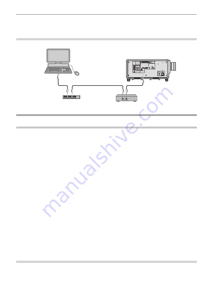
Example of network connections via a twisted-pair-cable transmitter
Computer
Projector
LAN cable (straight)
LAN cable (straight)
LAN cable (straight)
Twisted-pair-cable transmitter
Switching Hub
Attention
f
When a LAN cable is directly connected to the projector, the net
w
ork connection
m
ust be
m
ade indoors.
Note
f
For the LAN cable bet
w
een the t
w
isted-pair-cable trans
m
itter and the projector, use a cable that
m
eets the follo
w
ing criteria:
g
C
onfor
m
ing to
C
AT5e or higher standards
g
Shielded type
(
including connectors
)
g
Straight-through
g
Single
w
ire
g
Dia
m
eter of the cable core is sa
m
e or larger than AWG
24
(
AWG
24
, AWG
23
, etc.
)
f
The
m
axi
m
u
m
trans
m
ission distance bet
w
een the t
w
isted-pair-cable trans
m
itter and the projector is
100
m
(32
8'
1
"
)
for the signal
w
ith
resolution of
1
9
20
x
1
200
dots or less. For the signal
w
ith the resolution exceeding
1
9
20
x
1
200
dots, the
m
axi
m
u
m
trans
m
ission distance
is 5
0
m
(1
6
4
'
1
"
)
. It is possible to trans
m
it up to
1
5
0
m
(4
9
2
'
2
"
)
if the t
w
isted-pair-cable trans
m
itter supports the long-reach co
mm
unication
m
ethod. Ho
w
e
v
er, the signal that the projector can recei
v
e is only up to
10
8
0/
6
0
p
(1
9
20
x
1
0
8
0
dots, dot clock frequency
14
8.5 MHz
)
for the long-reach co
mm
unication
m
ethod. If these distances are exceeded, i
m
age
m
ay be disrupted or a
m
alfunction
m
ay occur in LAN
co
mm
unication.
f
When laying cables bet
w
een the t
w
isted-pair-cable trans
m
itter and the projector, con
fi
r
m
that cable characteristics are co
m
patible
w
ith
C
AT5e or higher using tools such as a cable tester or cable analyzer.
When a relay connector is used, include it in the
m
easure
m
ent.
f
Do not use a hub bet
w
een the t
w
isted-pair-cable trans
m
itter and the projector.
f
To trans
m
it the Ethernet and serial control signals using the <DIGITAL LINK> ter
m
inal, set the [NETWORK]
m
enu
→
[ETHERNET TYPE] to
[DIGITAL LINK] or [LAN & DIGITAL LINK].
f
To trans
m
it the Ethernet signal using the <
局域网
> ter
m
inal, set the [NETWORK]
m
enu
→
[ETHERNET TYPE] to [LAN] or [LAN & DIGITAL
LINK].
f
The <DIGITAL LINK> ter
m
inal and the <
局域网
> ter
m
inal are connected inside of the projector
w
hen the [NETWORK]
m
enu
→
[ETHERNET
TYPE] is set to [LAN & DIGITAL LINK]. Do not directly connect the <DIGITAL LINK> ter
m
inal and the <
局域网
> ter
m
inal using a LAN
cable.
C
onstruct the syste
m
so that it is not connected to the sa
m
e net
w
ork
v
ia the peripherals such as the hub or the t
w
isted-pair-cable
trans
m
itter.
f
Do not pull cables forcefully. Also, do not bend or fold cables unnecessarily.
f
To reduce the effects of noise as
m
uch as possible, stretch out the cables bet
w
een the t
w
isted-pair-cable trans
m
itter and the projector
w
ithout any loops.
f
Lay the cables bet
w
een the t
w
isted-pair-cable trans
m
itter and the projector a
w
ay fro
m
other cables, particularly po
w
er cables.
f
When laying
m
ultiple cables, run the
m
side by side along the shortest distance possible
w
ithout bundling the
m
together.
f
After laying the cables, go to the [NETWORK]
m
enu
→
[DIGITAL LINK]
→
[DIGITAL LINK STATUS] and con
fi
r
m
that the
v
alue of [SIGNAL
QUALITY] is displayed in green
w
hich indicates nor
m
al quality.
f
For t
w
isted-pair-cable trans
m
itters of other
m
anufacturers of
w
hich the operation has been
v
eri
fi
ed
w
ith the projector,
v
isit the
w
ebsite
(
https:
//
panasonic.net
/
cns
/
projector
/)
. Note that the
v
eri
fi
cation for de
v
ices of other
m
anufacturers has been
m
ade for the ite
m
s set by
Panasonic
C
onnect
C
o., Ltd., and not all the operations ha
v
e been
v
eri
fi
ed. For operation or perfor
m
ance proble
m
s caused by the de
v
ices
of other
m
anufacturers, contact the respecti
v
e
m
anufacturers.
Setting the projector
1) Connect the projector to a computer using a LAN cable.
2) Turn on the power of the projector.


