


Service the PA-7000 Series Firewall Hardware
STEP 4 |
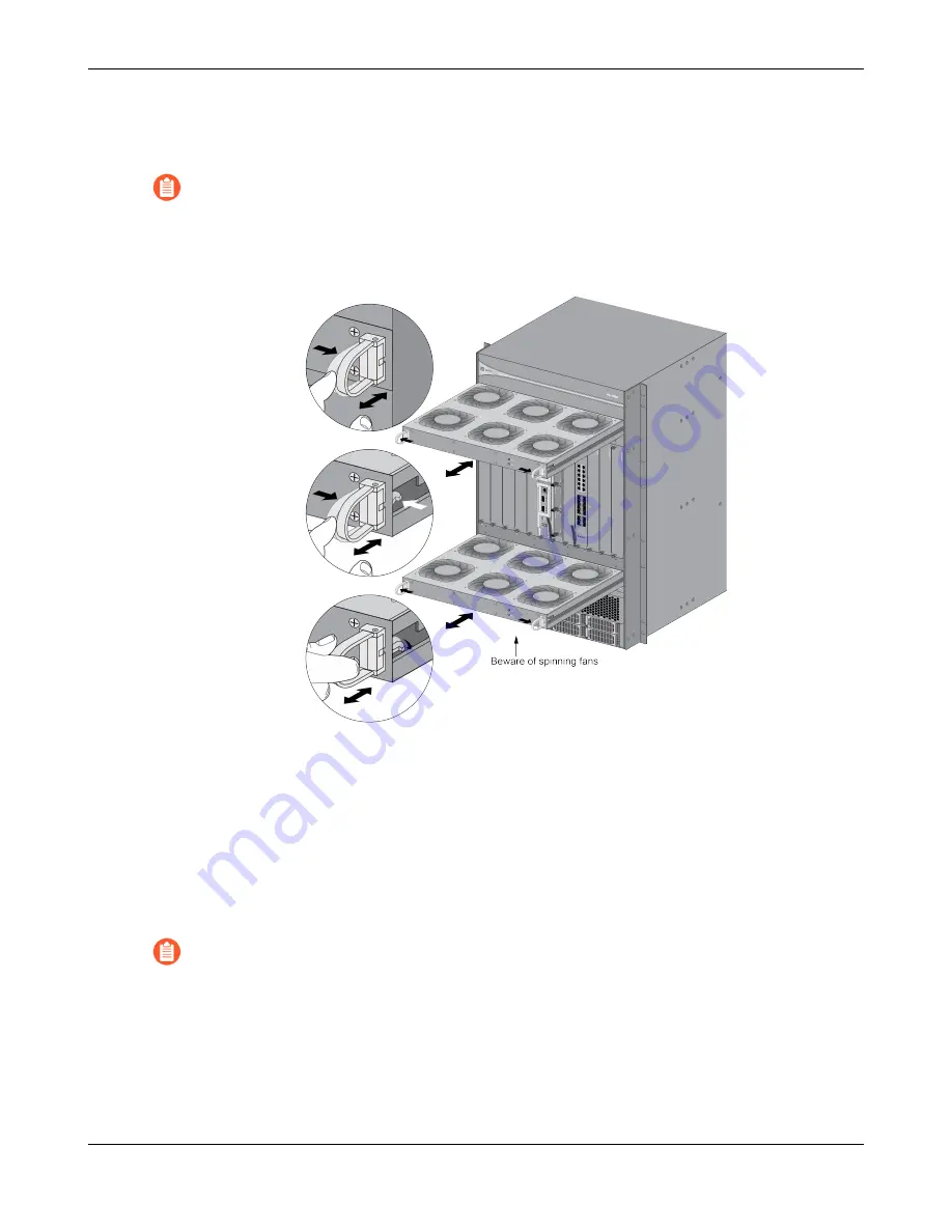
Grasp both handles on the failed fan tray and gently push them outward as you slide the fan
tray toward you about 1 inch. Wait 10 seconds to allow enough time for the working fans to
stop spinning.
Pushing the handles outward does not eject the fan tray; it unlocks the tray from the
chassis. Only a small amount of pressure is required to operate the release handles.
STEP 5 |
Verify that the front set of fans have stopped spinning and then continue to pull the fan tray
outward while supporting the back of the tray. Note that the fan tray weighs over 15 lbs., so
be prepared to support the weight of the tray.
STEP 6 |
Align the new fan tray with the empty fan tray slot rails and gently slide it in to the chassis
until it stops. You can do this by pushing on the handles or by pushing on the front panel of
the fan tray. As you fully seat the tray into place, the handles will click, indicating that the
tray is locked in place. The fan will then power on.
If the thermal protection circuit powers off the chassis due to over heating or failed
fans, you will need to turn the power off to the chassis and then restore power before
the chassis will power on again. On an AC model, you can turn off the power switches
located on the back of the chassis and then turn them back on or you can disconnect
the power cords and plug them back in. On a DC model, shut down the DC circuit to
the chassis and then restore power.
STEP 7 |
Verify that the fan tray is operational by noting the status of the fan tray LEDs and the FAN
LED on the SMC (slot 6). The Fault LED on the fan tray turns off, the Power LED on the fan
PA-7000 Series Firewall Hardware Reference
148
©
2023 Palo Alto Networks, Inc.


